Topologies of SIMATIC NET PROFIBUS Networks
2-8
PROFIBUS Networks SIMATIC NET
6GK1970-5CA20-0AA1 Release 2 05/2000
Bus Topologies
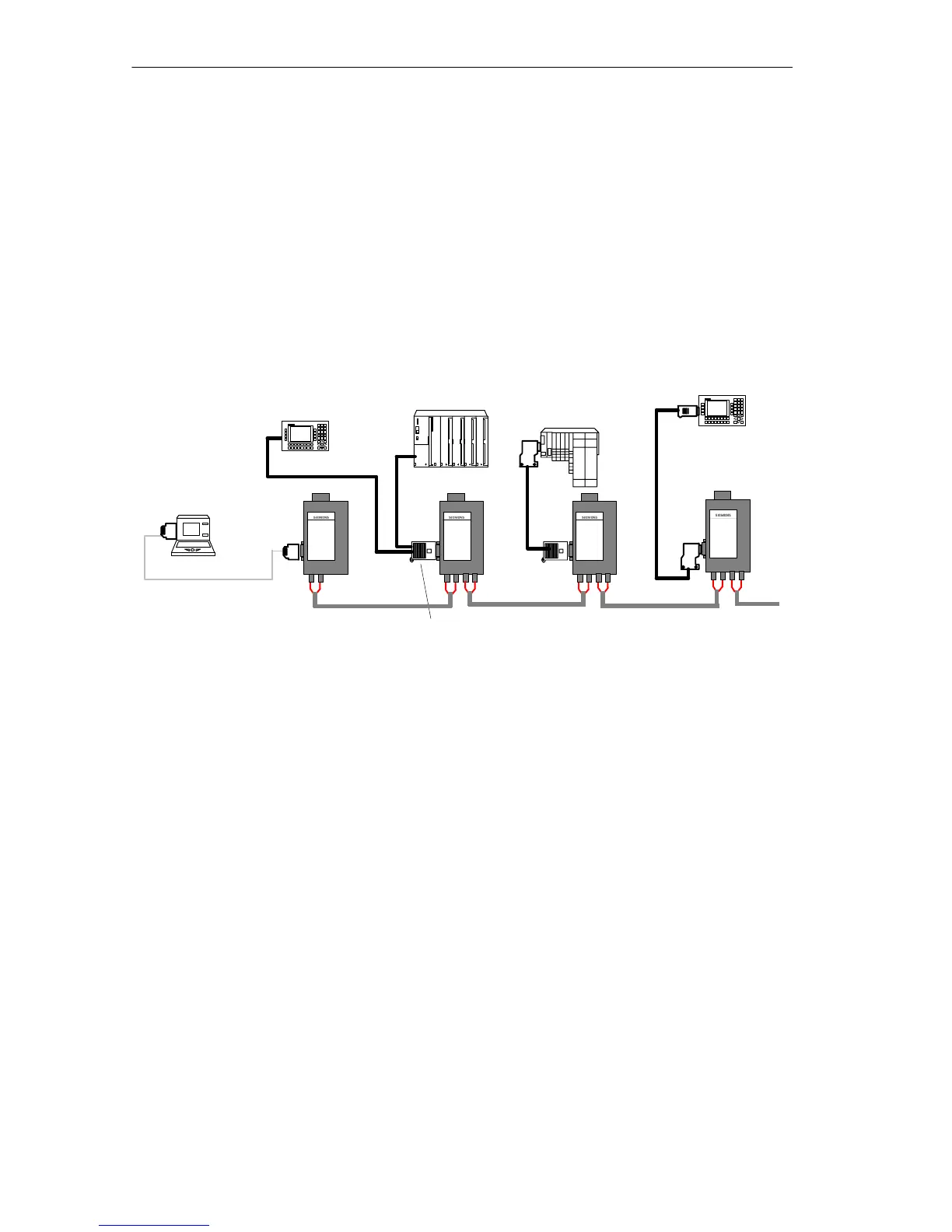
Figure 2-3 shows a typical example of a bus topology
In a bus structure, the individual SIMATIC NET PROFIBUS OLMs are connected
together in pairs by duplex fiber-optic cables.
At the start and end of a bus, OLMs with one optical channel are adequate, in
between, OLMs with two optical channels are required.
The DTEs are attached to the electrical interfaces of the OLMs. Either individual
DTEs or complete PROFIBUS segments with a maximum of 31 nodes can be
connected to the RS-485 interface.
2
2
Bus connector
ET 200S
PG
OP 25
Terminating resistor activated
ET 200M
1 FO cable
2 LAN cable for PROFIBUS
3 PROFIBUS 830-1T connecting cable
4 PROFIBUS 830-2 connecting cable
3
4
1
1
1
4
OP 25
Figure 2-3 Example of a Bus Topology with OLMs