Infrared Link Modul (ILM)6ZB5530–3AC30–0BA1
11
Copyright by Siemens
5.2.1 Point–to–Point–Link
Infrared
transmission link
0.5 to 15 m
PROFIBUS
master network segment
PROFIBUS
slave network segment
Slave
Master
Master
Master
Slave
Slave
Slave
ILM
ILM
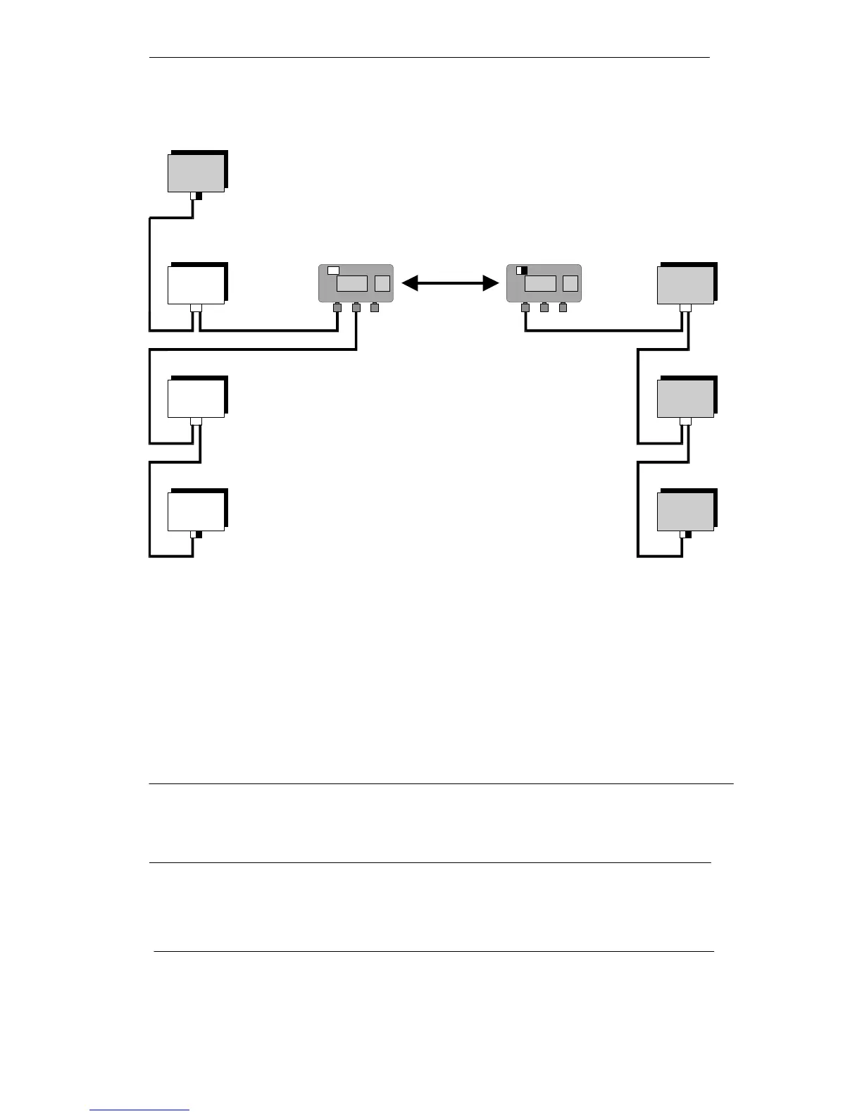
Figure 2: Point-to-Point Link with Two PROFIBUS ILMs
Figure 2 describes the typical layout of a PROFIBUS network with master and slave nodes and an infrared
transmission link with two PROFIBUS ILMs. The infrared transmission link is implemented as a point-to-point
link by the two PROFIBUS ILMs. In this situation, the two PROFIBUS ILMs replace a cable connection
between the two network segments. Remember that only slave nodes are permitted in the slave network
segments.
+ Make sure that the terminating resistors are activated at the segment ends (either in the bus
connector or in a PROFIBUS ILM).
Cascading is a further application for a point-to-point link.
Note
This “cascading with PROFIBUS ILM” mode is possible, but does involve a risk when operating PROFIBUS.
The transmission using an infrared link is generally more susceptible to problems than transmission via cable
(optical or electric).