Topologies of SIMATIC NET PROFIBUS Networks
2-18
PROFIBUS Networks SIMATIC NET
6GK1970-5CA20-0AA1 Release 2 05/2000
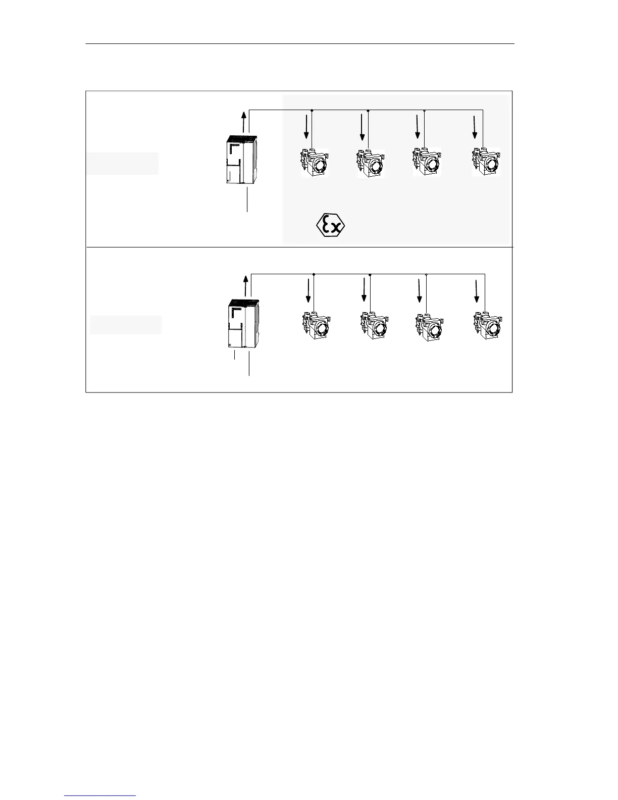
PROFIBUS-DP
PROFIBUS-PA
I
max
I
1
I
2
I
3...
...I
m
I
max
x 400 mA
24 V DC
Field device
1
Field device
2
Field device
3...
Field device
...m
DP/PA coupler
PROFIBUS-DP
PROFIBUS-PA
I
max
I
1
I
2
I
3...
...I
n
I
max
x 90 mA
24 V DC
Explosion-protected area
Field device
1
Field device
2
Field device
3...
Field device
...n
DP/PA coupler Ex [i]
Protection EEx [ia] II C
6ES7 157-0AD00-0XA0
I
max
x 110 mA
DP/PA coupler Ex [i]
Protection EEx [ib] II C
6ES7 157-0AD80-0XA0
6ES7 157-0ACx0-0XA0
Figure 2-12 Field Device Power Supply in the Hazardous and Non-Hazardous Area
Expansion
If the maximum output current of the DP/PA coupler is exceeded, you must include
a further DP/PA coupler.
Total Cable
The total cable is the total of the main cable and all the tap lines.
When using a standard PROFIBUS-PA cable with a cross-sectional area of
0.8 mm
2
, the maximum length of the total cable (with a maximum number of field
devices and worst-case positioning at the end of the cable) is as follows:
S 560 m for DP/PA coupler (6ES7 157-0AC00-0XA0)
S 680 m for DP/PA coupler (6ES7 157-0AD80-0XA0)
S 790 m for DP/PA coupler Ex [i] (6ES7 157-0AD00-0XA0)
Tap Line
The maximum permitted tap line lengths are listed in Table 2-2. You should also
remember the maximum length of the total cable (see above).