Analog Modules
4-109
Programmable Logic Controllers S7-300 Module Data
A5E00105505-03
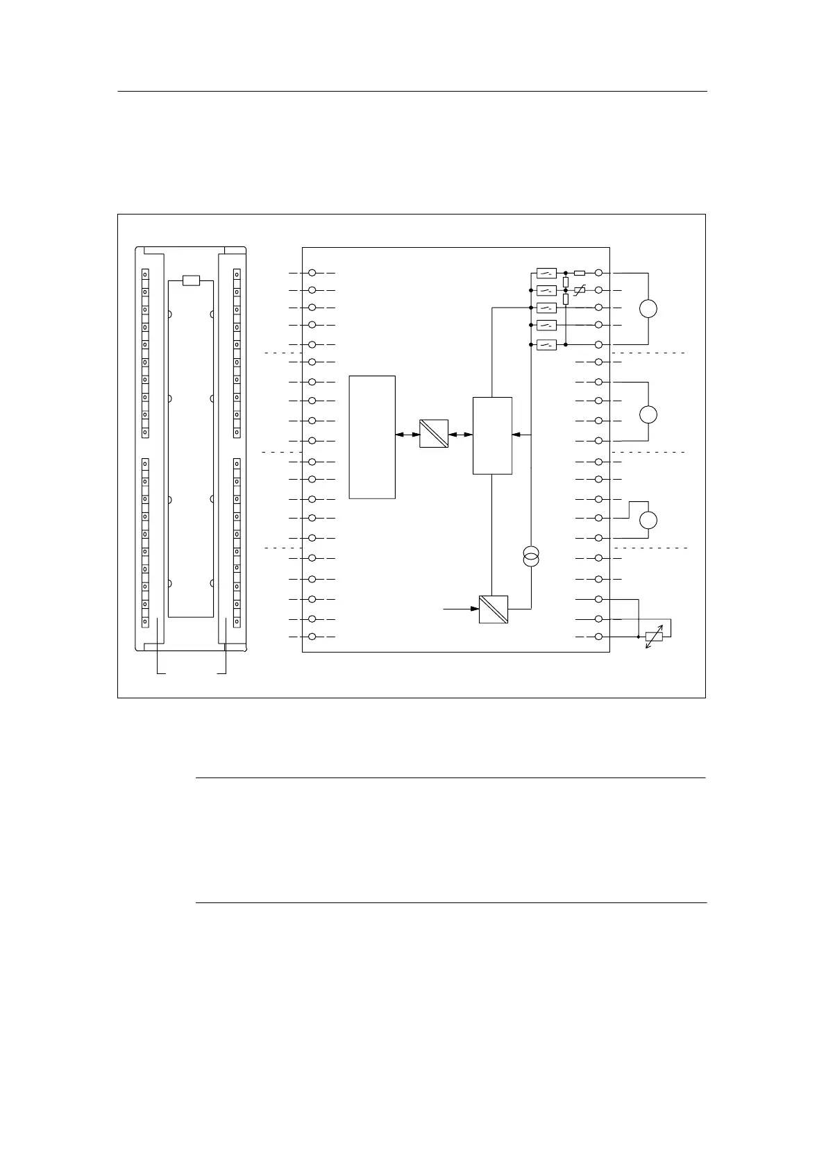
Terminal Connection Diagram and Block Diagram of the SM 331; AI 8 x 13 bits
The following figure shows some examples of connections for the different types of
measurements on channels 4 to 7. Basically, these connection examples apply to
all channels (channel 0 to 7).
S–
2
20
1
3
4
5
6
7
8
9
10
11
12
13
14
15
16
17
18
19
22
40
21
23
24
25
26
27
28
29
30
31
32
33
34
35
36
37
38
39
Channel
number
2
1
3
4
5
6
7
0
2
1
3
4
5
6
7
0
2
1
3
4
5
6
7
0
2
1
3
4
5
6
7
0
Logic
and
back-
plane
bus
ac-
tiva-
tion
ADC
Electrical
isolation
Internal supply
Current
source
+ 5 V from
backplane bus
Ch 0
Ch 1
Ch 2
Ch 3
M+
Connection example
Multiplexer
Ch 4
Ch 5
Ch 6
Ch 7
M–
M–
M+
M–
I+
M–
U+
A
mV
V
I+
M+
S–
U+
S–
M+
U+
I+
S–
U+
I+
M+
M–
M–
M+
I+
M–
U+
I+
M+
S–
U+
S–
M+
U+
I+
S–
U+
I+
S–
M–
Figure 4-39 Module View and Block Diagram of the Analog Input Module SM 331; AI 8 x 13
bits
Note
When connecting the voltage and current sensors, make sure that you do not
exceed the maximum permitted common-mode voltage U
CM
of 2 V between the
inputs. So to prevent measuring errors, interconnect the individual M– terminals.
It is not necessary to interconnect the M– terminals when measuring resistors and
resistance temperature detectors.

 Loading...


