SIMATIC TOP Connect and SIMATIC TOP Connect TPA
8-7
Programmable Logic Controllers S7-300 Module Data
A5E00105505-03
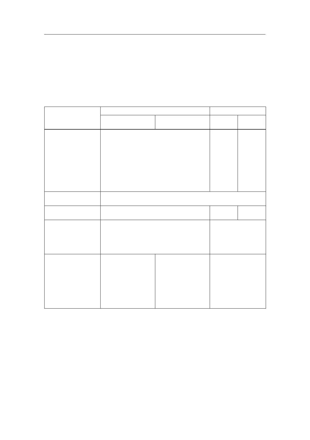
Wiring rules for connecting the supply voltage
The following table shows you what you have to consider when connecting the
module supply voltage to the terminal block or front connector module.
The terminals for the supply voltage are screws or spring-loaded terminals (refer to
Section 8.2.4 for handling spring-loaded terminals).
Table 8-3 Wiring Rules for Connecting the Supply Voltage
Rules for ...
Terminal block Front connector
Spring-loaded
connection
Screw-type
connection
Up to 4
Terminals
Up to 8
Terminals
Conductor
cross-sections suitable
for connection:
Solid conductors No No No
Stranded conductors
• Without end ferrules
• With end ferrules
0.25 to 1.5 mm
2
0.25 to 1.5 mm
2
0.25 to
1.5 mm
2
0.25 to
1.5 mm
2
0.25 to
0.75 mm
2
0.25 to
0.75 mm
2
No of conductors per
terminal
1 or combination of 2 conductors up to 1.5 mm
2
(sum) in a common
end ferrule
Max. diameter of
conductor insulation
∅ 3.1 mm ∅ 3.1 mm ∅ 2.0 mm
Length of conductor
insulation to be stripped
• Without insulation
collar
• With insulation collar
11 mm
11 mm
6 mm
–
End ferrules to
DIN 46228
• Without insulation
collar
• With insulation collar
– 0.25 to 1.0 mm
2
– 1.5 mm
2
Model A; up to 12 mm
long
Model E; up to 12 mm
long
Model E; 12 mm long
Model A; up to 12 mm
long
Model E; up to 12 mm
long
Model E; 18 mm long
Model A; 5 to 7 mm long
–

 Loading...


