Power Supply Modules
2-15
Programmable Logic Controllers S7-300 Module Data
A5E00105505-03
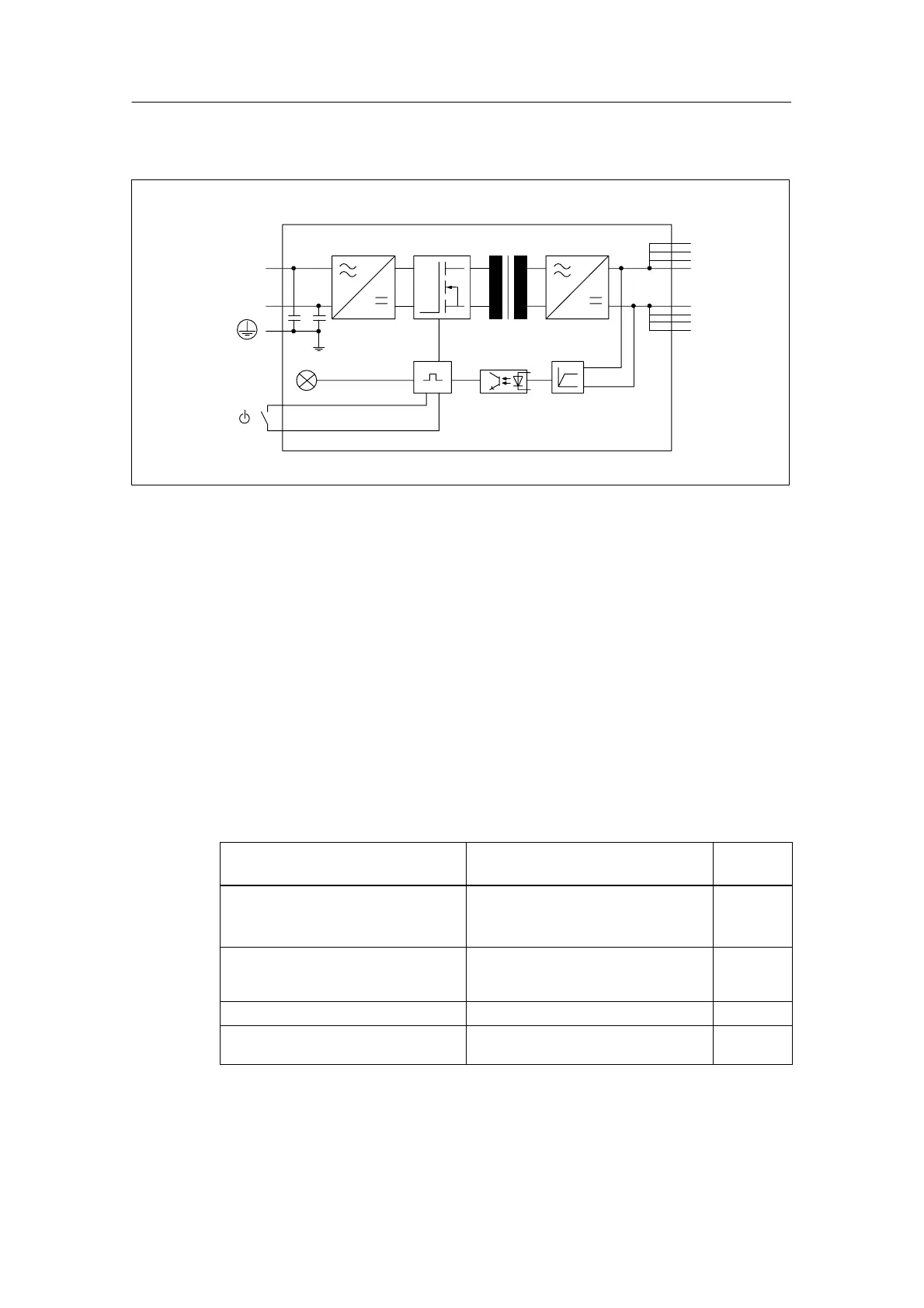
Basic circuit diagram of the PS 307; 10 A
L+
M
L1
N
24 VDC
U
I/
Figure 2-8 Basic Circuit Diagram of the PS 307 Power Supply Module (10 A)
Line protection
We recommend that you install a miniature circuit-breaker (MCB) (for example,
Siemens 5SN1 series) with the following rating to protect the incoming supply
cable of the PS 307 power supply module (10 A):
• Rated current at 230 VAC: 16 A
• Tripping characteristic (type): C.
Reaction to atypical operating conditions
Table 2-4 Reaction of the PS 307 Power Supply Module (10 A) to Atypical Operating
Conditions
If ... Reaction of the module 24 VDC
LED
... the output circuit is overloaded:
• I > 13 A (dynamic)
• 10 A < I v 13 A (static)
Voltage dip, autom. volt. recovery
Voltage drop, shortening of service life
Flashes
... the output is short-circuited Output voltage 0 V; automatic voltage
recovery after short circuit has been
eliminated
Dark
An overvoltage occurs on the primary side Possible destruction –
There is an undervoltage on the primary
side
Automatic disconnection; automatic voltage
recovery
Dark

 Loading...


