Special Signal modules
5-15
Programmable Logic Controllers S7-300 Module Data
A5E00105505-03
5.4.9 SM 338; POS-INPUT Addressing
Data range for the encoder values
The inputs and outputs of the SM 338 are addressed as of the initial module
address. The input and output address is determined at the configuration of the
SM 338 in STEP 7.
Input Addresses
Table 5-4 SM 338; POS-INPUT: Input Addresses
Encoder input
Input address (from the configuration) + address offset
0 ”Initial module address”
1 ”Module start address” + 4 bytes address offset
2 ”Module start address” + 8 bytes address offset
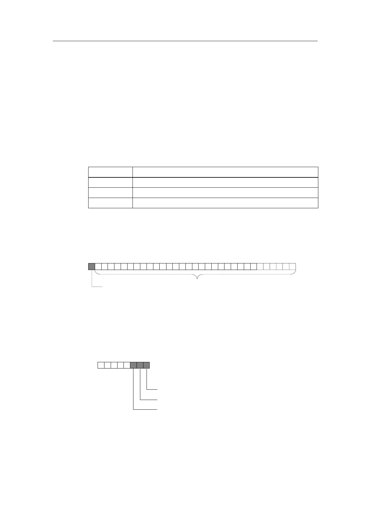
Structure of the double data word
For each encoder input the double data word is made up as follows:
Encoder value in gray or binary code
Freeze
0 = encoder value is not frozen. The value is constantly updated.
1 = encoder value is frozen. The value remains constant until
acknowledgment.
31 0
Output Address
Acknowledging the freeze function:
Bit 0 = encoder input 0
Bit 1 = encoder input 1
Bit 2 = encoder input 2
Initial module address
07
Reading out data areas
You can read out the data areas in your user program with the STEP 7-Operation L
PED “xyz”.

 Loading...


