Parameter Sets for Signal Modules
A-27
Programmable Logic Controllers S7-300 Module Data
A5E00105505-03
A.7 Parameters of the SM 331; AI 8 x 13 bits
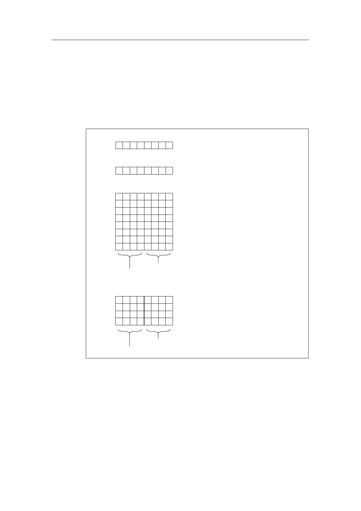
Structure of data record 1
The figure below shows the structure of data record 1 for the parameters of the
analog input module.
You activate a parameter by setting the corresponding bit in byte to “1”.
Byte 0
Byte 1
Interference suppression
Byte 2
Byte 3
Byte 4
Byte 5
Byte 6
Byte 7
Byte 8
Byte 9
Temperature measurement
Measuring method and measuring range channel 0
Measuring method and measuring range channel 1
Measuring method and measuring range channel 2
Measuring method and measuring range channel 3
Measuring method and measuring range channel 4
Measuring method and measuring range channel 6
Measuring method and measuring range channel 7
Measuring method and measuring range channel 5
70432 165
70432 165
70432 165
Byte 10 Temperature coefficient channel 0 and 1
Byte 11 Temperature coefficient channel 2 and 3
Byte 12 Temperature coefficient channel 4 and 5
Byte 13 Temperature coefficient channel 6 and 7
70432 165
Channel 0, 2, 4, 6
Channel 1, 3, 5, 7
Measuring Method
Measuring Range
Figure A-12 Data Record 1 for Parameters of the Analog Input Modules

 Loading...


