Digital modules
3.12 Digital input module SM 321; DI 16 x DC 24/125 V; with hardware and diagnostic interrupts (6ES7321-
7EH00-0AB0)
S7-300 Module data
100 Manual, 06/2017, A5E00105505-AJ
Special features of diagnostics
The SM 321; DI 16 x DC 24 V/125 V supplies 9-byte diagnostic data (diagnostic data set 0
with a length of 4 bytes and the diagnostic data set 1 with a length of 9 bytes).
The wire-break diagnostics is only reported in the channel error vector of the data set 1
(bytes 7 and 8). Each channel that reports an error in the channel errror vector has a wire-
break. You can find additional information, in chapter Structure and content of diagnostics
data, byte 0 and up (Page 584).
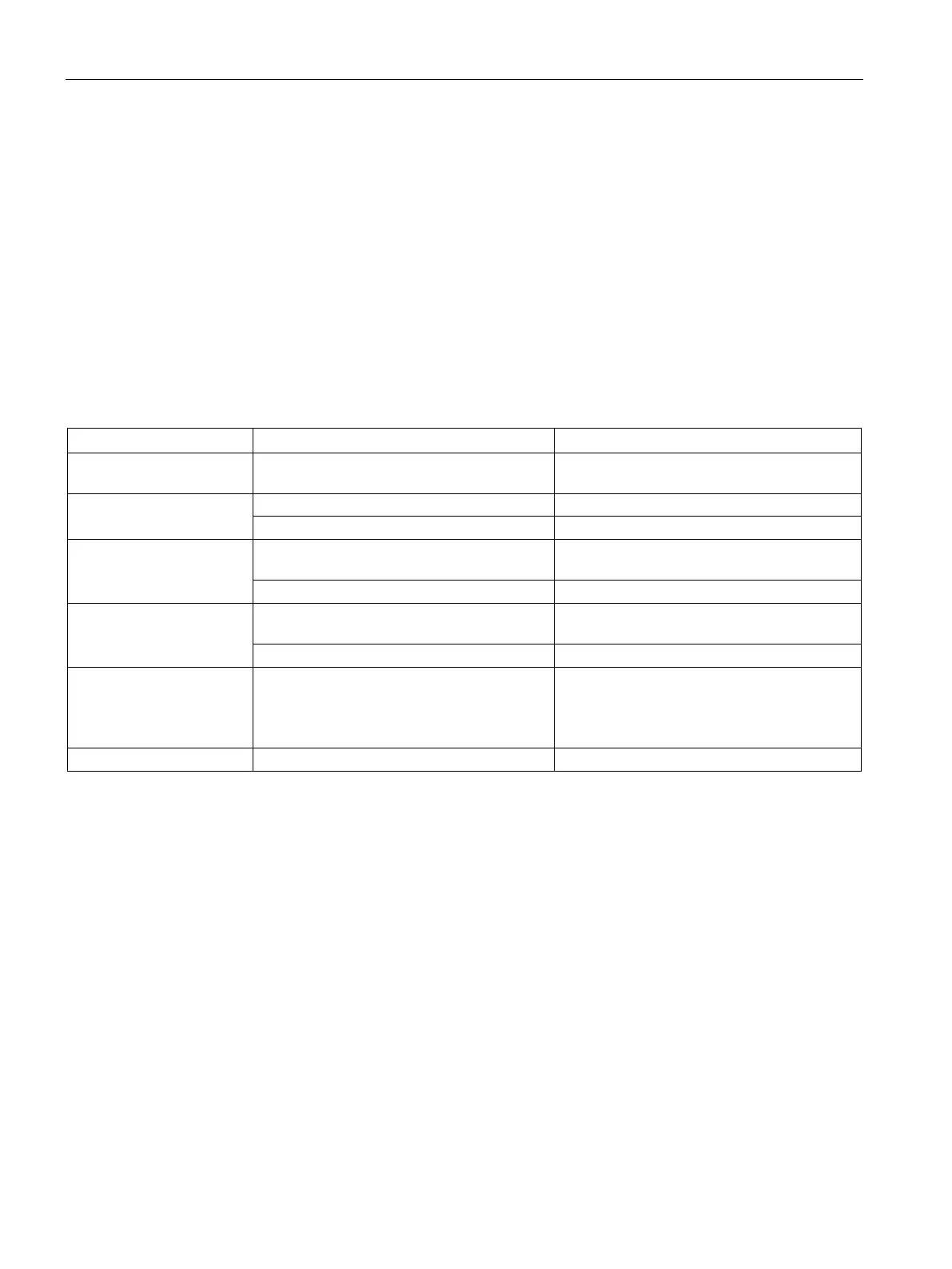
Causes of error and troubleshooting
Table 3- 20 Diagnostics messages of SM 321; DI 16 x DC 24 V/125V, causes of error and troubleshooting
To correct or avoid error
Incorrect module parame-
Implausible parameter or combination thereof Program the module
Time monitoring activated
(watchdog)
Infrequent high electromagnetic interference Eliminate the interference
EPROM fault Infrequent high electromagnetic interference Eliminate interference and cycle the power
RAM fault Infrequent high electromagnetic interference Eliminate interference and cycle the power
Hardware interrupt lost The module can not output an interrupt, be-
cause the previous interrupt was not
acknowledged; possibly a configuration error
Change interrupt processing in the CPU, and
reprogram the module as required
The error persists until the module is assigned
new parameters
3.12.3 Interrupts of SM 321; DI 16 x DC 24/125 V
Introduction
This chapter describes the interrupt reaction of SM 321; DI 16 x DC 24 V/125V. Always
distinguish between the following interrupts:
● Diagnostic interrupt
● Hardware interrupt
For detailed information on the OBs and SFCs mentioned below, refer to the STEP 7 Online
Help.