Digital modules
3.12 Digital input module SM 321; DI 16 x DC 24/125 V; with hardware and diagnostic interrupts (6ES7321-7EH00-0AB0)
S7-300 Module data
Manual, 06/2017, A5E00105505-AJ
99
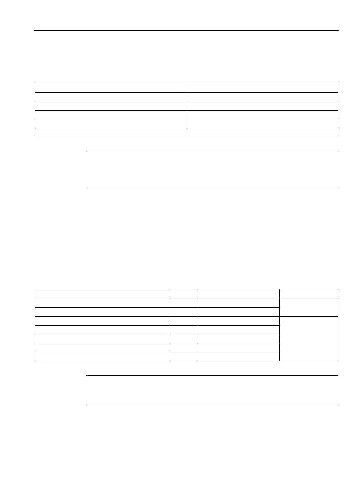
Tolerances of the programmable input delays
Table 3- 18 Tolerances of the input delays of SM 321; DI 16 x DC 24 V/125 V
0.5 ms 580 μs to 700 μs
Note
The timers for the input delay are only valid for reading in the status. In the case of wire
-
-break diagnostics" is only triggered approx. 40 ms after the reading in of the
3.12.2 Diagnostics of SM 321; DI 16 x DC 24/125 V
Diagnostic messages of SM 321; DI 16 x DC 24 V/125 V
The table below shows an overview of the diagnostic messages of SM
321; DI 16 x DC 24 V/125 V.
Table 3- 19 Diagnostic messages of SM 321; DI 16 x DC 24 V/125 V
No/incorrect parameters in module
No
Time monitoring activated (watchdog)
Note
To detect the errors indicated by programmable diagnostic messages, you must have
programmed t
he digital module accordingly in STEP 7.