Digital modules
3.12 Digital input module SM 321; DI 16 x DC 24/125 V; with hardware and diagnostic interrupts (6ES7321-
7EH00-0AB0)
S7-300 Module data
98 Manual, 06/2017, A5E00105505-AJ
Configuration in RUN
Special considerations must be given if you use the Configuration in RUN function.
SF LED is lit:
Status before re-configuration diagnostics on, SF LEDs lit among others (on CPU, IM or
module), although diagnostics are no longer pending and the module is operating correctly.
Solution:
● Only change the configuration when no diagnostics are pending for the module or
● Pulling and plugging the module.
3.12.1 Parameters of SM 321; DI 16 x DC 24/125 V
Programming
The general procedure of programming digital modules is described in the chapter
Programming digital modules.
Parameters of SM 321; DI 16 x DC 24 V/125 V
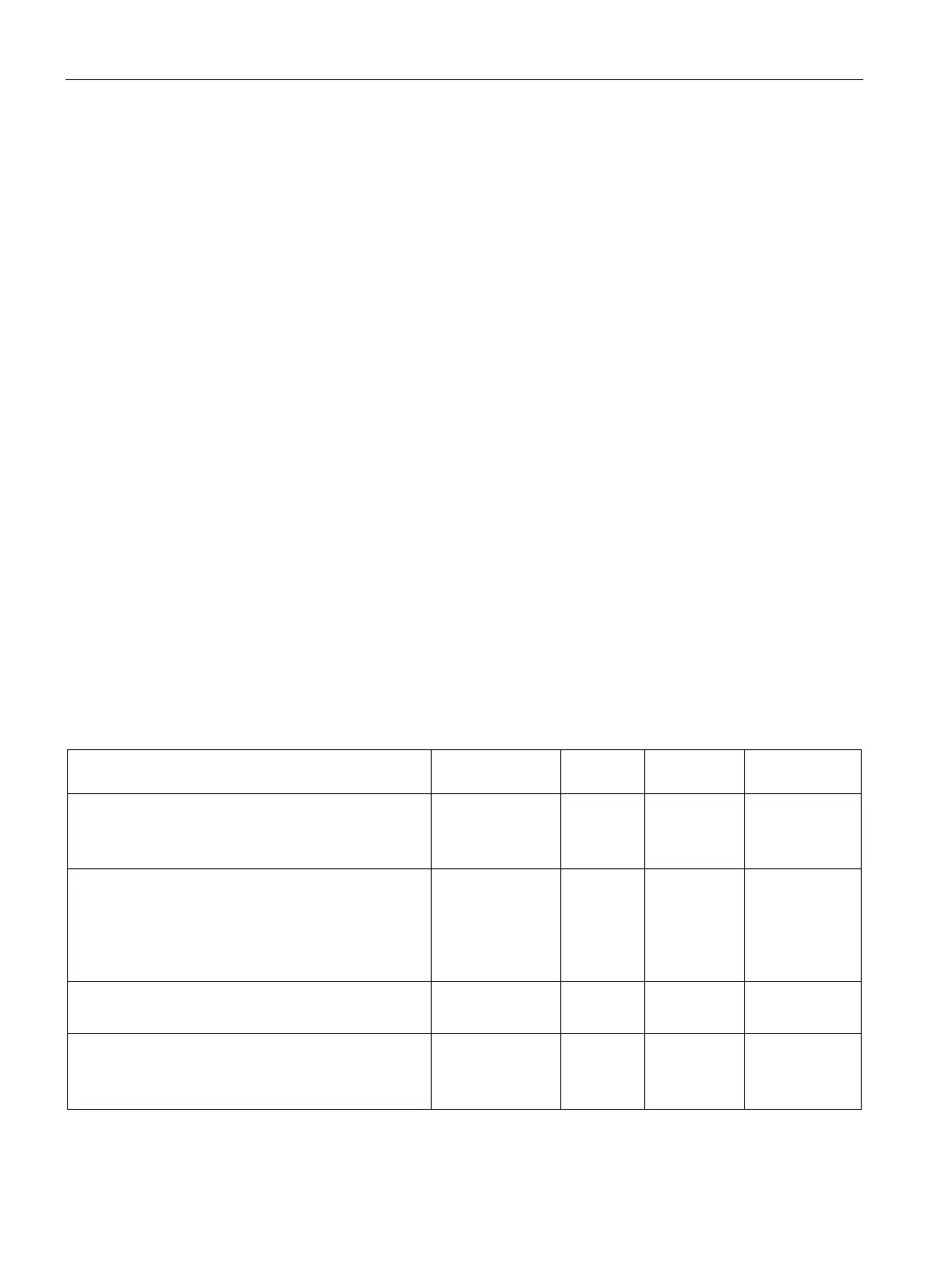
The table below shows an overview of configurable parameters and their default settings for
SM 321; DI 16 x DC 24 V/125V.
The default settings apply if you have not set any parameters in STEP 7.
Table 3- 17 Parameters of SM 321; DI 16 x DC 24 V/125 V
Enable
• Diagnostic interrupt
• Hardware interrupt
Yes/No
Yes/No
No
No
dynamic
Module
Input delay/voltage type 0.1 ms (DC)
0.5 ms (DC)
3 ms (DC)
15 ms (DC)
3 ms (DC) static Module
Diagnostics
• Wire break
Yes/No
No
static
Channel
Hardware interrupt trigger
• Positive edge
• Negative edge
Yes/No
Yes/No
No
No
dynamic
Channel