Digital modules
3.12 Digital input module SM 321; DI 16 x DC 24/125 V; with hardware and diagnostic interrupts (6ES7321-7EH00-0AB0)
S7-300 Module data
Manual, 06/2017, A5E00105505-AJ
97
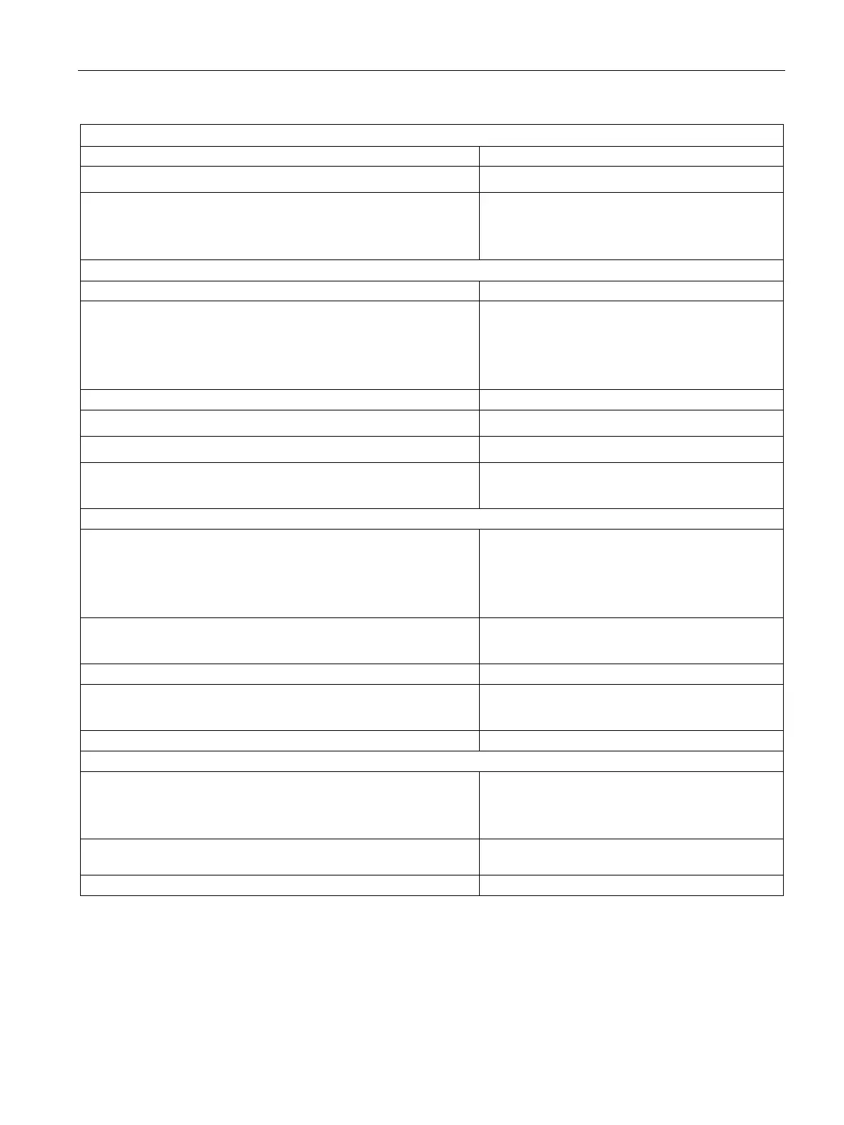
• from the backplane bus
max. 90 mA
Power loss of the module
• L+ = 24 V
• L+ = 100 V
typ. 2 W
typ. 6.5 W
Status, interrupts, diagnostics
Interrupts
• Hardware interrupt
• Diagnostic interrupt
• Wire break
programmable
programmable
programmable
• Group error display
red LED (SF)
• Reading diagnostics information
supported
Monitoring for
• Wire break
yes, sensing I < 1 mA
Input voltage
• Rated value
• "1" signal
• "0" signal
From 15 to 146 V
from -146 V to + 5 V
Input current
• "1" signal
Typ. 3.5 mA
Connection of 2-wire BEROs
• Permissible quiescent current
supported
max. 1 mA
Wiring of the signal transmitters
with 40-pin front connector
Input delay
• programmable
• Rated value
Yes
typ. 0.1/0.5/3/15/20 ms**
Fixed current limitation of the sensor for wire-break detection See previous table for dependence on rated input
Dehnconnect RK DCO RK ME110; Art. No. 919 923
* To obtain a time stamp accuracy of < 1 ms, the input delay must be configured to 0.1 ms.
** To obtain a high immunity to interference, use a shielded cable and set input delay to 0.1 ms.