Digital modules
3.26 Digital output module SM 322; DO 16 x UC 24/48 V; (6ES7322-5GH00-0AB0)
S7-300 Module data
164 Manual, 06/2017, A5E00105505-AJ
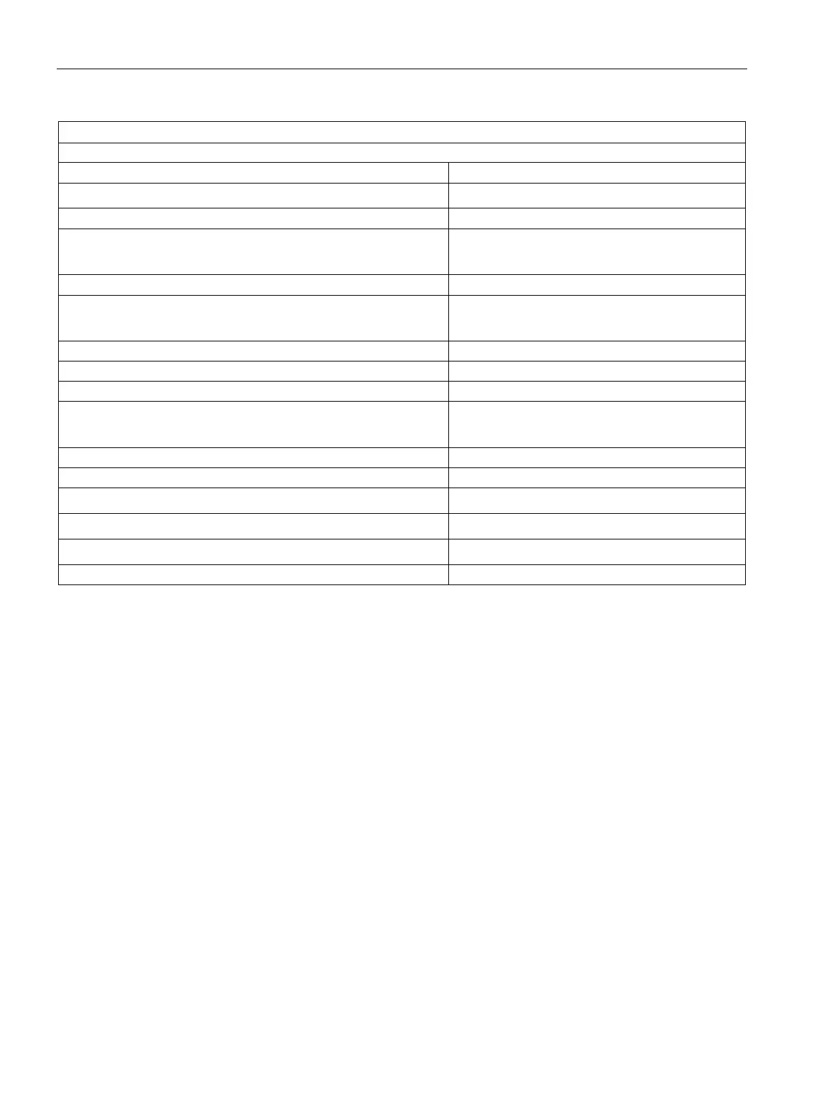
Output voltage
• "1" signal
min. L+ (-0.25 V)
Output current
• Rated inrush current (per group) with "1" signal
• "0" signal (residual current)
0.5 A max. 1.5 A (max. 50 ms)
max. 10 μA
Output delay (resistive load)
• "0" to "1" transition
• "1" to "0" transition
max. 6 ms
max. 3 ms
External fuse for relay outputs
2 t
2
Internal parallel wiring of 2 outputs
• for redundant load control
• for performance increase
supported
not supported
Control of a digital input
• with resistive load
max. 10 Hz
• with inductive load to IEC 947-5-1; DC 12 AC/12
max. 0.5 Hz
• with lamp load
max. 0.5 Hz
using a 40pin front connector
* Outputs must be protected by a 250 V fast-blow fuse (recommended fuses: Wickman
194-1100 1.1 A and Littlefuse 0217-800 V 800 mA.)
When mounted in a hazardous area to National Electric Code (NEC), always remove the
fuse when the module is outside of the potentially explosive atmosphere, and use a suitable
tool.
Configuration in RUN
Special considerations must be given if you use the Configuration in RUN function.
SF LED is lit:
Status before re-configuration diagnostics on, SF LEDs lit among others (on CPU, IM or
module), although diagnostics are no longer pending and the module is operating correctly.
Solution:
● Only change the configuration when no diagnostics are pending for the module or
● Pulling and plugging the module.