Digital modules
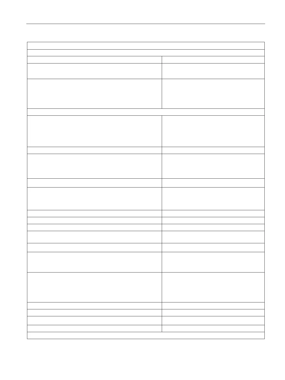
3.29 Digital output module SM 322; DO 8 x DC 24 V/ 0.5 A; with diagnostics interrupt; (6ES7322-8BF00-0AB0)
S7-300 Module data
Manual, 06/2017, A5E00105505-AJ
177
Status, interrupts, diagnostics
Status display green LED per channel
Interrupts
• Diagnostic interrupt
programmable
Diagnostic functions
• Group error display
• Channel error display (F)
• Reading diagnostics data
programmable
red LED (SF)
red LED (F) per channel
supported
Output voltage
• "1" signal
without series diode
min. L + (- 0.8 V)
min. L+ (-1.6 V)
• "1" signal
Rated value
0.5 A
10 mA to 0.6 A
1)
• "0" signal (residual current)
max. 0.5 mA
Output delay (resistive load)
• "0" to "1" transition
• "1" to "0" transition
max. 180 μs
max. 245 μs
Wiring two outputs in parallel
• for redundant load control
Only outputs with series diode and common refer-
• for performance increase
not supported
Control of a digital input supported
1 binary input to IEC 61131, Type 2;
Type 1, with disabled wire-break monitoring
Switching frequency
• with resistive load
• with inductive load to IEC 947-5-1, DC 13
• with lamp load
max. 100 Hz
max. 2 Hz
max. 10 Hz
Internal limiting of the inductive shutdown voltage to
Short-circuit protection of the output
• Threshold
typ. 0.75 A to 1.5 A
using a 20-pin front connector
1) 5 mA to 0.6 A, with disabled wire-break monitoring