Digital modules
3.35 Relay output module SM 322; DO 8 x Rel. 230VAC/5A; (6ES7322-5HF00-0AB0)
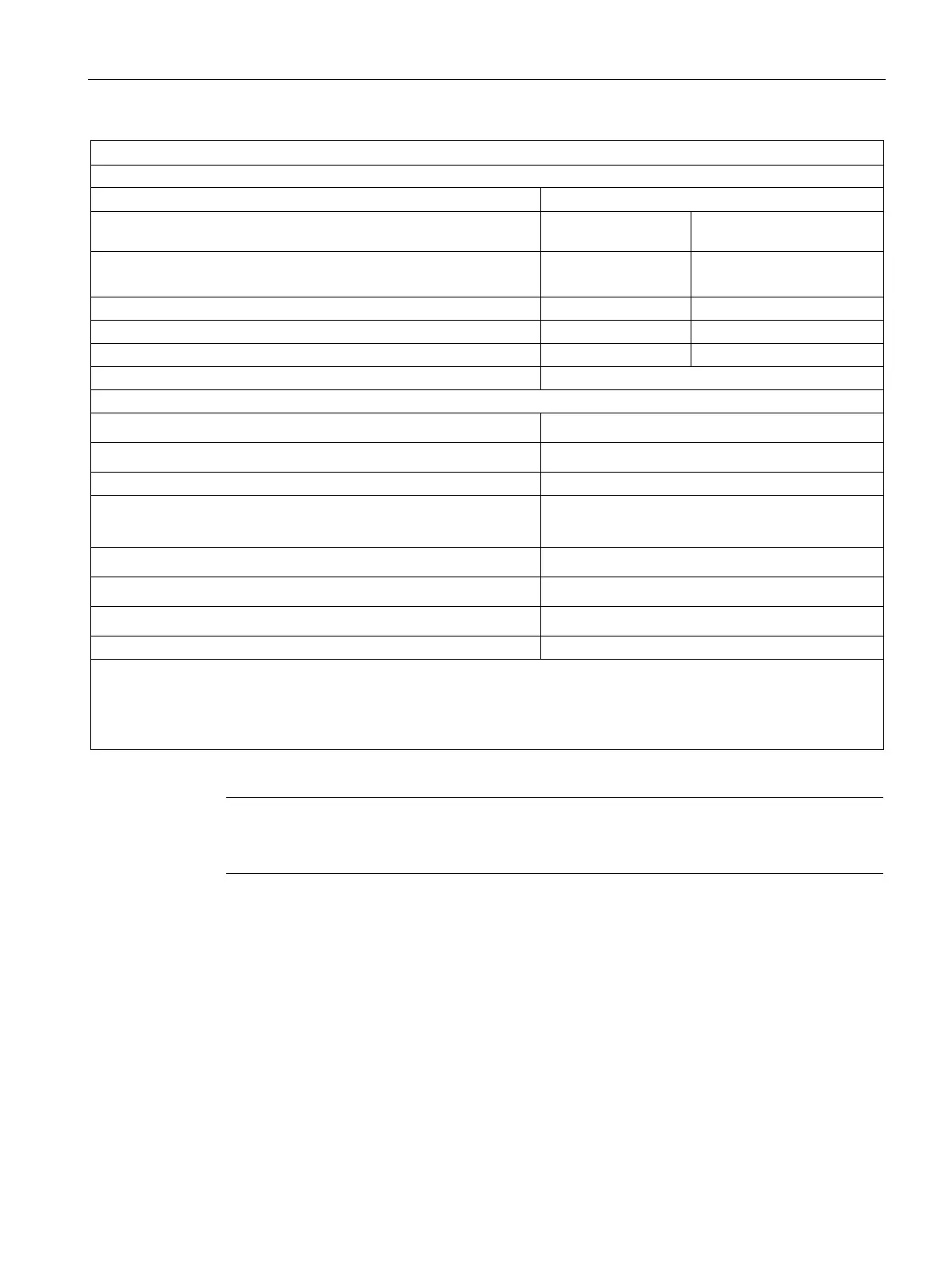
S7-300 Module data
Manual, 06/2017, A5E00105505-AJ
213
An RC quenching element (jumper "SJ" inserted) or an external protection circuit extend the service life of contacts.
Size of the motor starter max. size 5 to NEMA
Power No. of switching cycles
Lamp load (230 V AC) 1000 W
25000
Energy-saving lamps/fluorescent lamps with electronic ballast
3)
Fluorescent lamps, conventionally compensated
Fluorescent lamps, non-compensated
RC quenching element; 330 Ω, 0.1 µF
Wiring two outputs in parallel
• for redundant load control
supported (only outputs with the same load voltage)
• for performance increase
not supported
Control of a digital input
Switching frequency
• Mechanical
max. 10 Hz
• with resistive load
max. 2 Hz
• with inductive load to IEC 947-5-1, DC13/AC15
max. 0.5 Hz
• with lamp load
max. 2 Hz
using a 40-pin front connector
1)
Without inserted jumper (SJ).
2)
With AC load voltage and inserted jumper (SJ). No residual current if the jumper (SJ) is not installed.
3)
The sum of all inrush currents on a ballast connected to an output must not
Note
The residual current of an RC quenching element connected to IEC Type 1 inputs may
cause unwanted signal st
ates. Remove the SJ jumper to rectify this fault.
Configuration in RUN
Special considerations must be given if you use the Configuration in RUN function.
SF LED is lit:
Status before re-configuration diagnostics on, SF LEDs lit among others (on CPU, IM or
module), although diagnostics are no longer pending and the module is operating correctly.
Solution:
● Only change the configuration when no diagnostics are pending for the module or
● Pulling and plugging the module.