Analog modules
6.2 Module overview
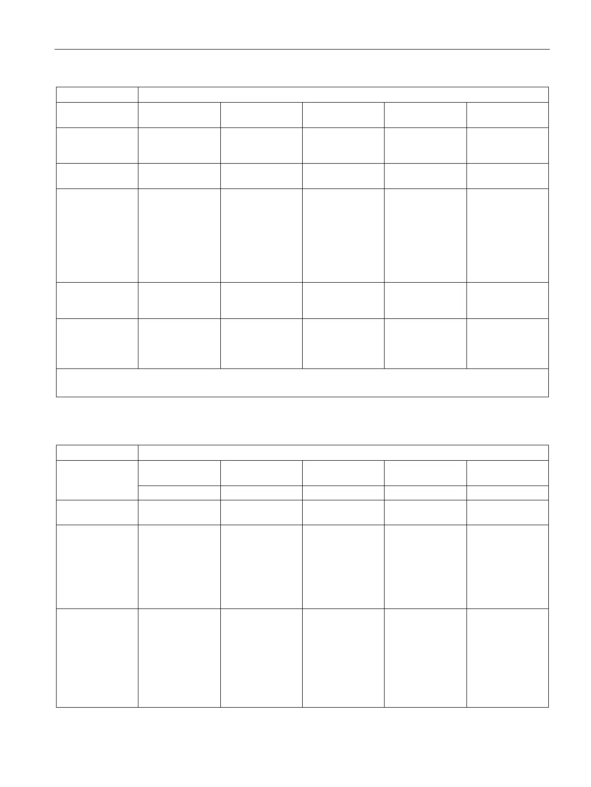
S7-300 Module data
Manual, 06/2017, A5E00105505-AJ
303
Limit value moni-
programmable for
programmable for
programmable for
no programmable for
Hardware interrupt
when limit ex-
programmable programmable programmable no Programmable
Hardware interrupt
no yes no No no
Potential ratios
from:
• The backplane
bus interface
from:
• The backplane
bus interface
from:
• The backplane
bus interface
• The load volt-
age (not for 2-
DMU)
electrically isolated
from:
• The backplane
bus interface
from:
• the CPU
• The load volt-
age (not for 2-
DMU)
maximum potential
difference be-
50 V DC 60 V DC 11 V DC 2.0 V DC ≤ DC 2.3 V
Special features - - - Motor protection
with PTC and
silicone tempera-
-
Z sign
2-DMU = 2-wire transducer
Table 6- 2 Analog input modules (continued)
SM 331; AI 8 x
0/4...20 mA HART
Number of inputs 2 inputs in 1 chan-
6 inputs in 1 chan-
8 inputs in 4 chan-
8 inputs in 4 chan-
8 inputs in 1 chan-
Resolution programmable for
each channel
group:
• 9 bits+sign
• 12 bits+sign
• 14 bits+sign
Programmable for
each channel
group:
• 15 bits+sign
Programmable for
each channel
group:
• 15 bits+sign
Programmable for
each channel
group:
• 15 bits+sign
programmable for
each channel
group:
15 bits+sign
Measurement type programmable for
each channel
group:
• Voltage
• Current
• Resistance
• Temperature
Programmable for
each channel
group:
• Voltage
• Temperature
programmable for
each channel
group:
• Temperature
programmable for
each channel
group:
• Resistance
• Temperature
Programmable for
each channel
group:
• Current