Analog modules
6.3 Analog input module SM 331; AI 8 x 16 bit; (6ES7331-7NF00-0AB0)
S7-300 Module data
Manual, 06/2017, A5E00105505-AJ
309
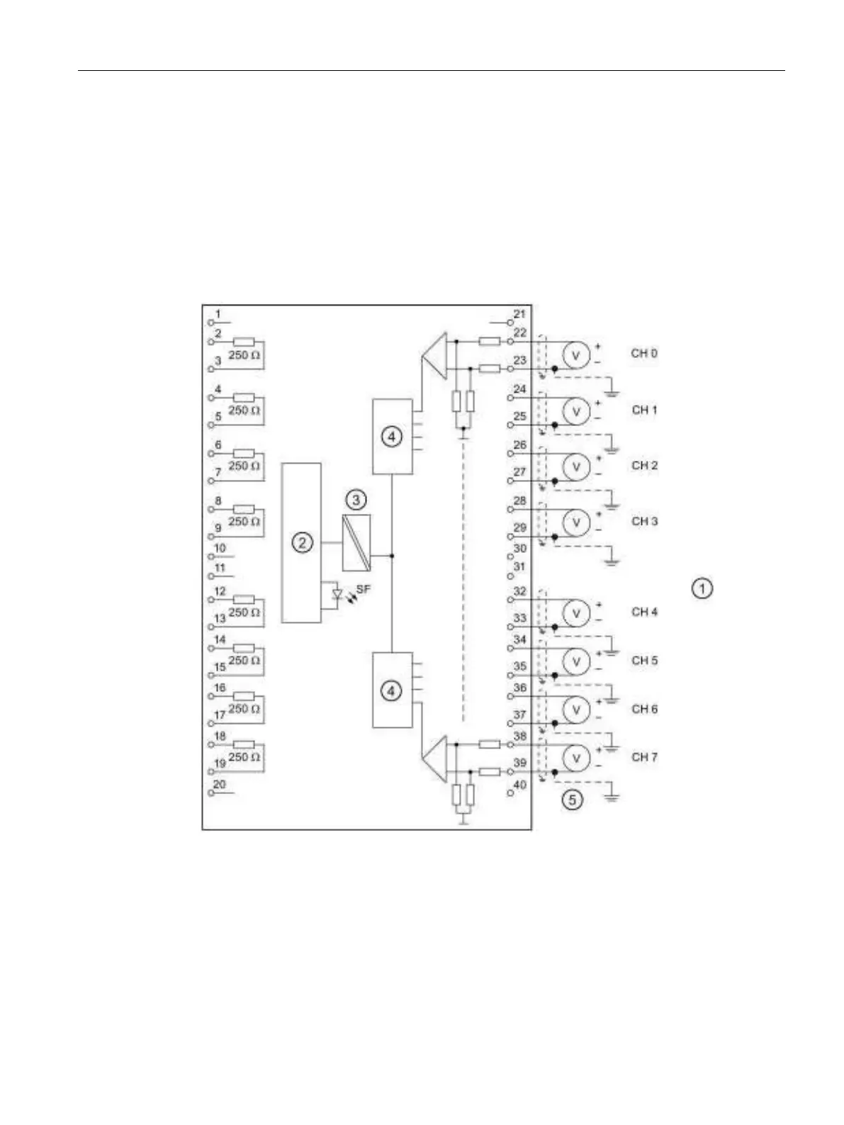
Wiring: Voltage and current measurement
Wire the voltage inputs of the channel voltage in parallel using the corresponding shunt
resistor when measuring current. Bridge the channel input terminals with the adjacent
connector terminals.
Example: You configure channel 0 for current measurement by bridging terminals 22 and 2,
and terminals 23 to 3.
At the channel configured for current measurements, connect the shunt resistor to the
adjacent channel terminals in order to achieve the specified precision.
Analog-to-Digital Converter (ADC)
Figure 6-1 Wiring and block diagram