Analog modules
6.3 Analog input module SM 331; AI 8 x 16 bit; (6ES7331-7NF00-0AB0)
S7-300 Module data
316 Manual, 06/2017, A5E00105505-AJ
Line continuity check
The line continuity check is available for the 1 V to 5 V and 4 mA to 20 mA ranges.
Rule for both measuring ranges:
When the line continuity check is enabled, the module logs the wire-break to diagnostics
data when the current drops below 3.6 mA (0.9 V.)
The module also triggers a diagnostic interrupt if this function is enabled in the program.
A wire break can only be signaled by means of the lit SF LED and the diagnostic bytes must
be evaluated in the user program if diagnostic interrupts are disabled.
When line continuity check is
disabled and diagnostic interrupts are enabled, the module
triggers a diagnostic interrupt when underflow is detected.
Special features in programming high and low limits
The programmable limits (hardware interrupt triggers) of SM 331; AI 8 x 16 Bit differ from the
range of value shown in the
Overview of parameters of SM 331; AI 8 x 16 Bit.
table.
Reason: The calculation methods deployed in the module software to evaluate the process
variables do not allow the reporting of values up to 32511 in certain situations. The process
value triggering a hardware interrupt at underflow or overflow limits is based on the
calibration factors of the relevant channel, and may vary between the low limits shown in the
table below and the value 32511 (7EFF
H
).
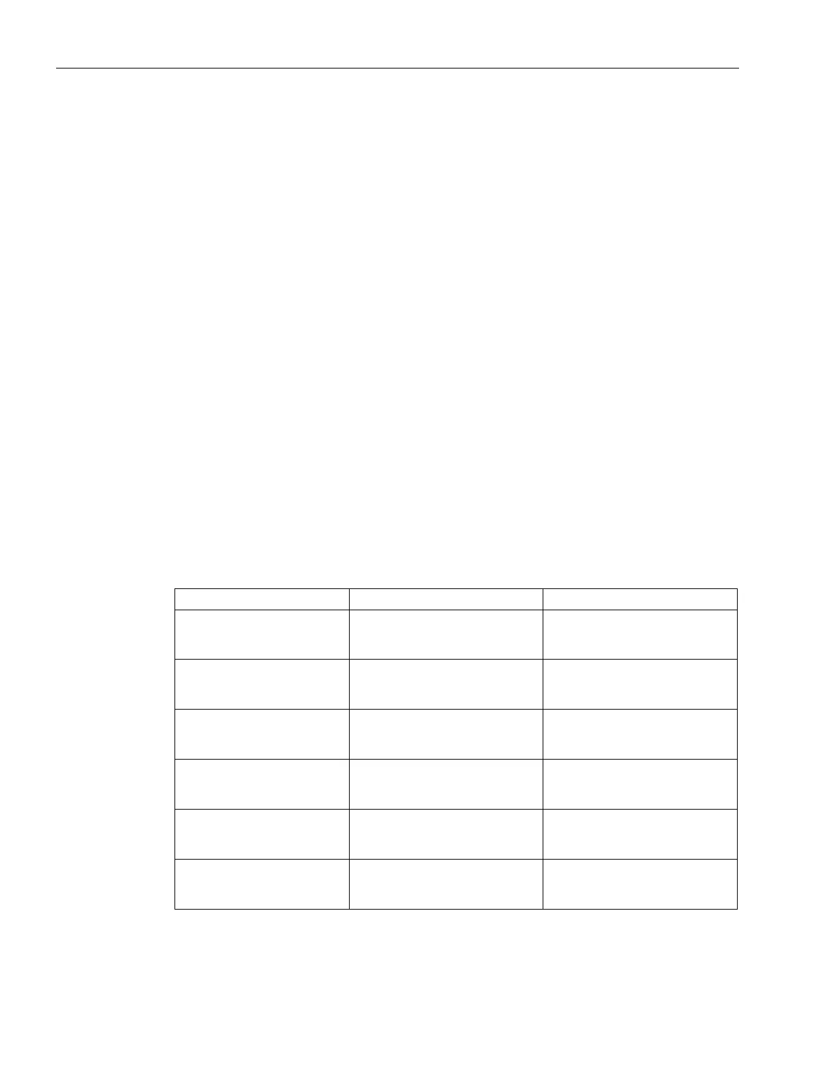
You may not define any limits which exceed the minimum limits specified in the table below.
Table 6- 8 Minimum high and low limits of SM 331; AI 8 x 16 Bit
± 10 V 11.368 V
31430
H
-11.369 V
-31433
H
± 5 V 5.684 V
31430
-5.684 V
-31430
1 V to 5 V 5.684 V
32376
H
0.296 V
-4864
H
0 mA to 20 mA 22.737 mA
31432
-3.519 mA
-4864
4 mA to 20 mA 22.737 mA
32378
H
1.185 mA
-4864
H
± 20 mA 22.737 mA
31432
-22.737 mA
-31432