EasyManuals Logo

Siemens SIMATIC User Manual

Siemens SIMATIC
648 pages
To Next Page IconTo Next Page
To Previous Page IconTo Previous Page
Page #355 background imageLoading...
Page #355 background image
Analog modules
6.7 Analog input module SM 331; AI 8 x 12 bit;(6ES7331-7KF02-0AB0)
S7-300 Module data
Manual, 06/2017, A5E00105505-AJ
355
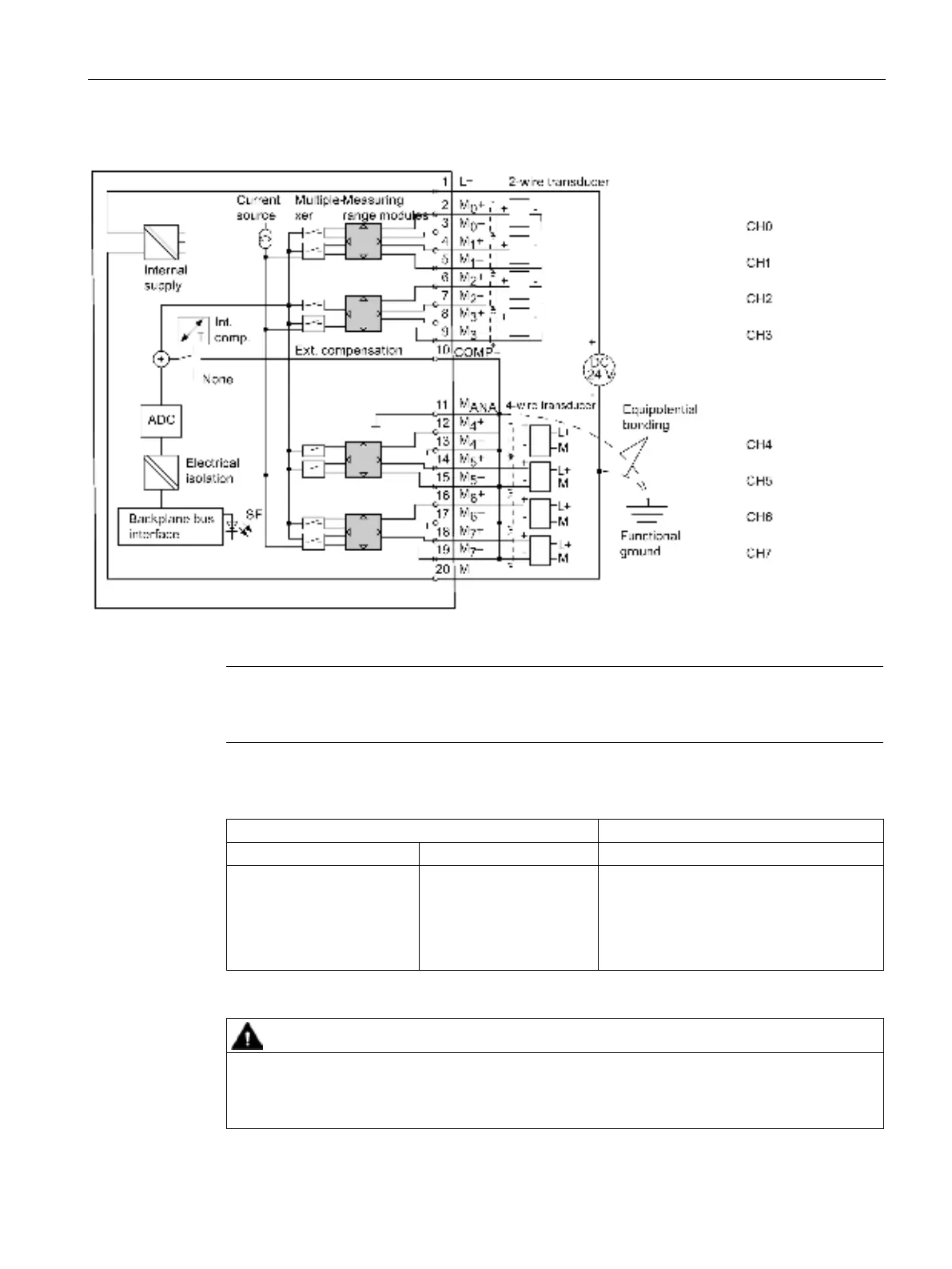
Wiring: 2-wire and 4-wire transducers for current measurement
Figure 6-14 Block diagram and wiring diagram
Note
The interconnection between M
ANA
and M- (terminals 11, 13, 15, 17, 19) is not required when
using grounded 4
-wire transducers with non-isolated supply.
Measuring range module settings
Measuring range
Measuring range module setting
2-wire transducer
4 mA to 20 mA
D
4-wire transducer
± 3.2 mA
± 10 mA
0 mA to 20 mA
4 mA to 20 mA
± 20 mA
C
CAUTION
Measuring range module in "Current" position
Any voltage measurement will destroy the measuring range module if "current" measuring
mode is set.

Table of Contents

Other manuals for Siemens SIMATIC

Questions and Answers:

Question and Answer IconNeed help?

Do you have a question about the Siemens SIMATIC and is the answer not in the manual?

Siemens SIMATIC Specifications

General IconGeneral
Product type designationSIMATIC
CPUVaries by model
MemoryVaries by model
Input/OutputVaries by model
CommunicationVaries by model
Programming LanguageSTEP 7
Operating Temperature0°C to 60°C (varies by model)
Protection ClassIP20
CategoryProgrammable Logic Controller (PLC)

Related product manuals