Analog modules
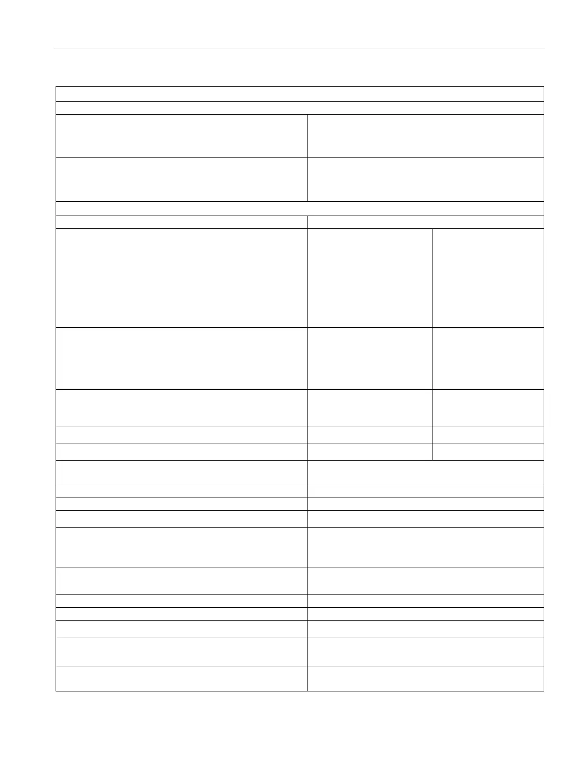
6.7 Analog input module SM 331; AI 8 x 12 bit;(6ES7331-7KF02-0AB0)
S7-300 Module data
Manual, 06/2017, A5E00105505-AJ
361
Status, interrupts, diagnostics
• Limit interrupt
• Diagnostic interrupt
Channels 0 and 2
programmable
• Group error display
• Reading diagnostics information
red LED (SF)
supported
Input ranges (rated values) / input impedance
• Voltage
± 250 mV
± 500 mV
± 1,000 mV
± 2.5 V
± 5 V
1 V to 5 V
10 MΩ
10 MΩ
10 MΩ
100 kΩ
100 kΩ
100 kΩ
• Current
± 10 mA
± 20 mA
0 mA to 20 mA
25 Ω
25 Ω
25 Ω
• Resistance
300 Ω
10 MΩ
• Thermocouples
• Resistance thermometer
Maximum voltage at voltage input (destruction limit)
75 V for the duration of max. 1 s (duty factor 1:20)
Maximum current at current input (destruction limit)
Wiring of the signal transmitters
using a 20-pin front connector
• for voltage measurement
• for current measurement
as 2-wire transducer
supported
supported
• For thermoresistor/resistance measurement
Supported, cable resistances are not compensated
Supported, cable resistances are not compensated
Supported, cable resistances are compensated
• Load of the 2-wire transducer
Characteristics linearization
• for thermocouples
Types E, N, J, K, L
• for resistance thermometers
Pt 100 (Standard and Klima range)
Ni 100 (Standard and Klima range)