Analog modules
6.9 Analog input module SM 331; AI 8 x RTD; (6ES7331-7PF01-0AB0)
S7-300 Module data
Manual, 06/2017, A5E00105505-AJ
381
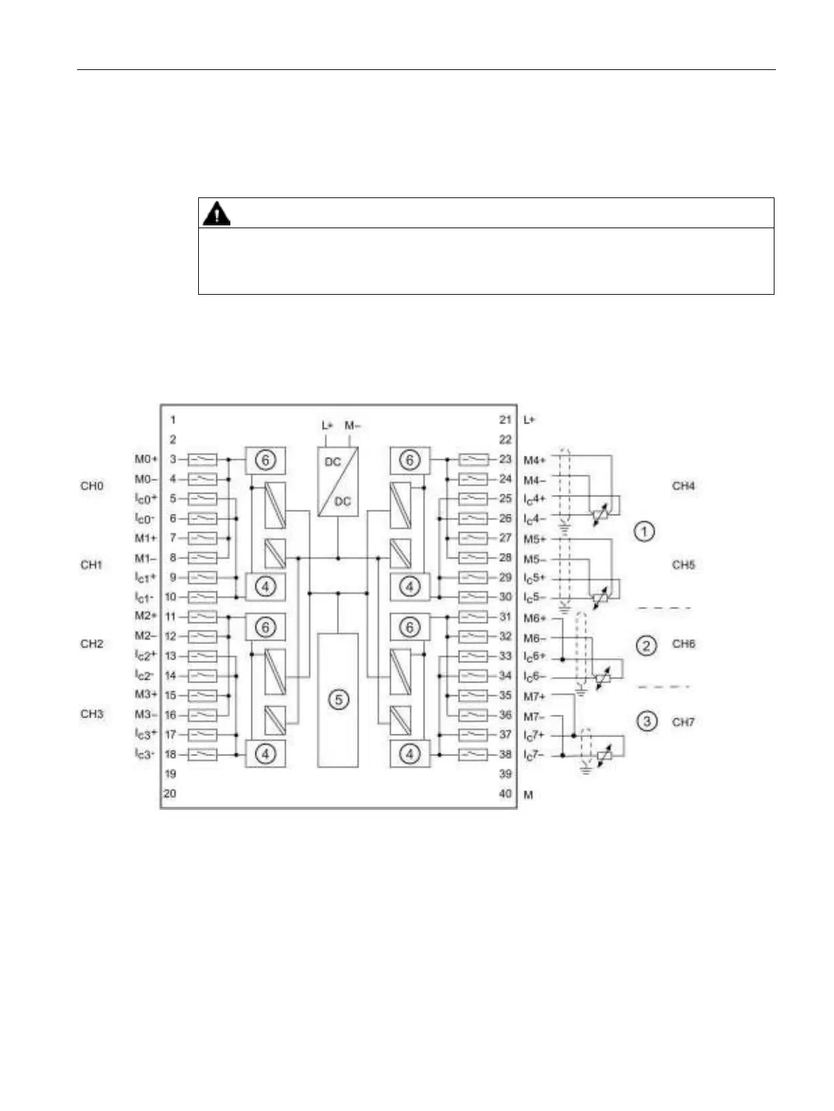
Pin assignment
The figures below show the various connection options. These connection examples apply to
all channels (channels 0 to 7).
Incorrect wiring of the 3-wire connection can result in unpredictable operation of the module
and dangerous conditions in the plant.
Wiring: 2, 3 and 4-wire connection for resistance and thermal resistance measurement
Connection possible at both sides to channels 0 to 7
Analog-to-digital converter (ADC)
Figure 6-21 Wiring and block diagram