Parameter sets of signal modules
A.12 Parameters of analog output modules
S7-300 Module data
Manual, 06/2017, A5E00105505-AJ
575
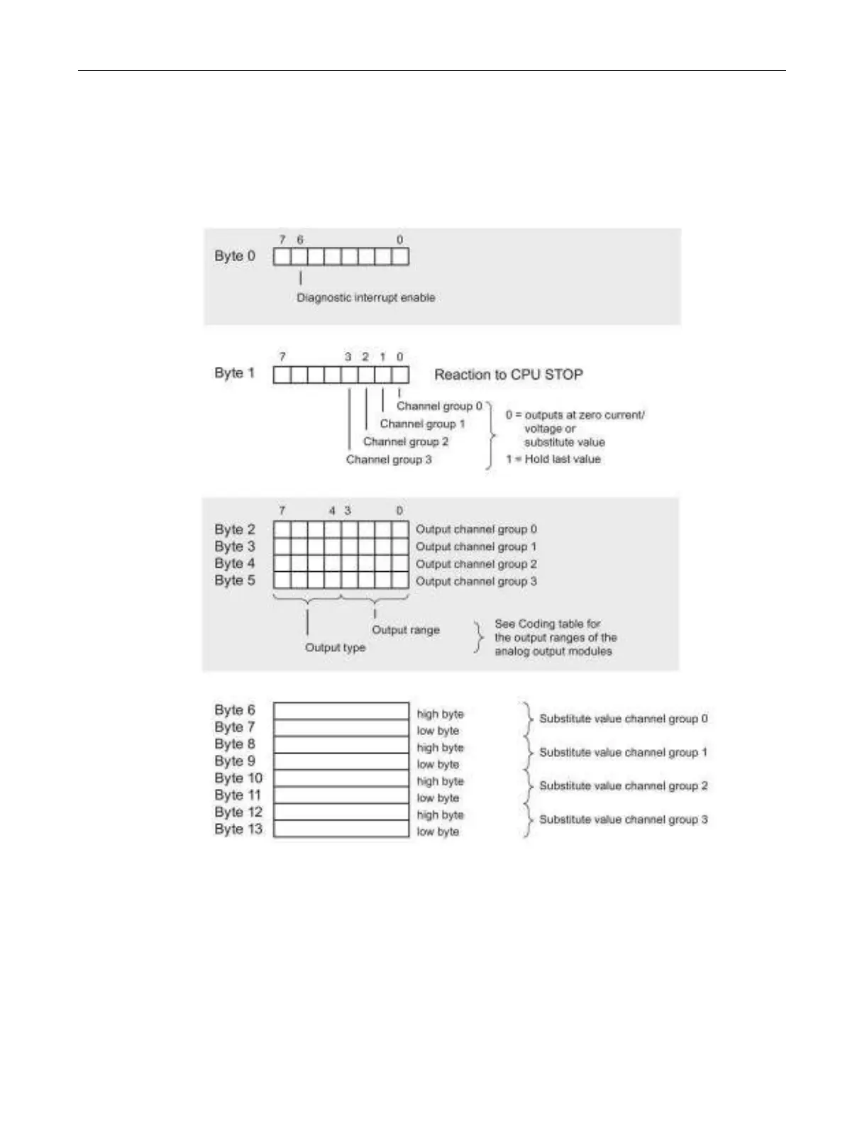
Structure of data record 1
The figure below shows the structure of data record 1 for the parameters of analog output
modules.
You enable diagnostic interrupts by setting a logic "1" at the corresponding bit of byte 0.
Figure A-25 Data record 1 for the parameters of analog output modules