Home
Siemens
Control Unit
SIMATIC
Page 594
Siemens SIMATIC - Page 594
648 pages
Manual
Save Page as PDF
To Next Page
To Next Page
To Previous Page
To Previous Page
Loading...
Diagnostic
s data
of signal
modules
B.5
Dia
gnostics
data of SM
331; AI 6 x
TC isola
ted
S7
-
300 Module data
594
Manual
,
06/2017
,
A5E00105505
-
AJ
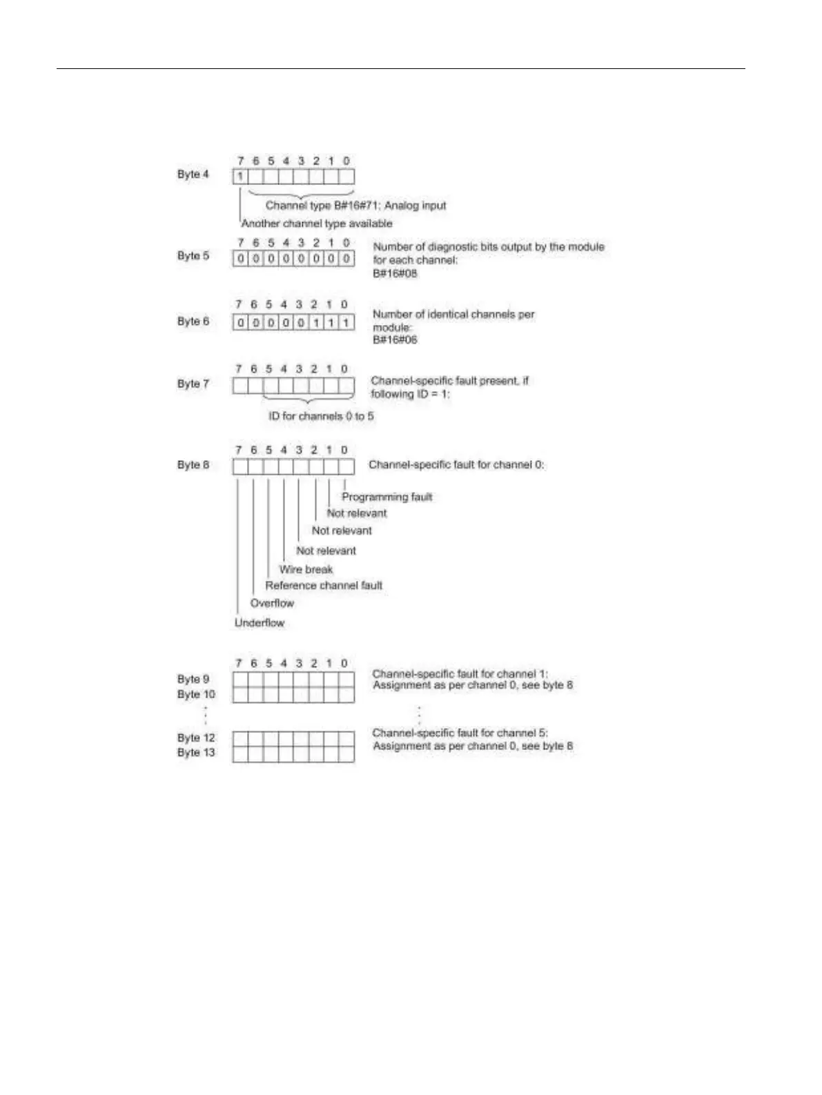
Byt
e 4
t
o by
t
e 13 (
diagnostic
dat
a
r
ecor
d 1)
Figure
B-
10
Diagnosti
c data recor
d 1
593
595
Table of Contents
Main Page
Preface
3
Table of Contents
7
General Technical Data
14
Standards and Approvals
14
Electromagnetic Compatibility
19
Shipping and Storage Conditions for Modules and Backup Batteries
21
1.4 Mechanical and Climatic Environmental Conditions for S7-300 Operation
23
Specification of Dielectric Tests, Protection Class, Degree of Protection, and Rated Voltage of S7-300
25
Rated Voltages of S7-300
25
SIPLUS S7-300 Modules
26
1.8 Environmental Conditions for the Operation of SIPLUS S7-300 Modules
30
Power Supply Modules
32
Power Supply Module PS 307; 2 A; (6ES7307-1BA01-0AA0)
33
Power Supply Module PS 307; 5 A; (6ES7307-1EA01-0AA0)
36
Power Supply Module PS 307; 10 A; (6ES7307-1KA02-0AA0)
39
Power Supply Module PS 305; 2 A; (6AG1305-1BA80-2AA0)
42
Power Supply Module PS 307; 5 A; (6AG1307-1EA80-2AA0)
45
Digital Modules
48
Module Overview
49
Digital Input Modules
49
Digital Output Modules
52
Relay Output Modules
55
Digital IO Modules
56
Steps in Selecting and Commissioning the Digital Module
57
Programming Digital Modules
58
Diagnostics of Digital Modules
59
How to Protect Digital Modules from Inductive Overvoltage
61
Digital Input Module SM 321; DI 64 X DC 24 V, Sinking/Sourcing; (6ES7321-1BP00-0AA0)
63
Digital Input Module SM 321; DI 32 X DC 24 V; (6ES7321-1BL00-0AA0)
70
Digital Output Module SM 321; DI 32 X AC 120 V; (6ES7321-1EL00-0AA0)
73
Digital Input Module SM 321; DI 16 X DC 24 V; (6ES7321-1BH02-0AA0)
76
Digital Input Module SM 321; DI 16 X DC 24 V High Speed; (6ES7321-1BH10-0AA0)
78
Digital Input Module SM 321; DI 16 X 24 VDC; with Hardware and Diagnostic Interrupts (6ES7321-7BH01-0AB0)
80
Isochronous Mode
85
SM 321; DI 16 X DC 24 V - Parameters
86
SM 321; DI 16 X DC 24 V - Diagnostics
88
SM 321; DI 16 X DC 24 V - Behavior
90
SM 321; DI 16 X DC 24 V - Interrupts
91
Digital Input Module SM 321; DI 16 X DC 24/125 V; with Hardware and Diagnostic Interrupts (6ES7321-7EH00-0AB0)
94
Parameters of SM 321; DI 16 X DC 24/125 V
98
Diagnostics of SM 321; DI 16 X DC 24/125 V
99
Interrupts of SM 321; DI 16 X DC 24/125 V
100
Digital Input Module SM 321; DI 16 X DC 24 V; Source Input; (6ES7321-1BH50-0AA0)
103
Digital Input Module SM 321; DI 16 X UC 24/48 V; (6ES7321-1CH00-0AA0)
105
Digital Input Module SM 321; DI 16 X DC 48-125 V; (6ES7321-1CH20-0AA0)
108
Digital Input Module SM 321; DI 16 X AC 120/230 V; (6ES7321-1FH00-0AA0)
111
Digital Input Module SM 321; DI 8 X AC 120/230 V; (6ES7321-1FF01-0AA0)
114
Digital Input Module SM 321; DI 8 X AC 120/230 V ISOL; (6ES7321-1FF10-0AA0)
117
Digital Output Module SM 322; DO 64 X DC 24 V/0.3 a Sourcing; (6ES7322-1BP00-0AA0)
120
Digital Output Module SM 322; DO 64 X DC 24 V/0.3 a Sinking (6ES7322-1BP50-0AA0)
128
Digital Output Module SM 322; DO 32 X DC 24 V/ 0.5 A; (6ES7322-1BL00-0AA0)
135
Digital Output Module SM 322; DO 32 X AC 120/230 V/1 A; (6ES7322-1FL00-0AA0)
139
Digital Output Module SM 322; DO 16 X DC 24 V/ 0.5 A; (6ES7322-1BH01-0AA0)
143
Digital Output Module SM 322; DO 16 X DC 24 V/0.5 A: (6ES7322-8BH10-0AB0)
147
Parameters of Digital Output Modules
152
Diagnosis of Digital Output Modules
153
Firmware Update Via HW Config
154
I&M Identification Data
155
Digital Output Module SM 322; DO 16 X DC 24 V/0.5 a High Speed; (6ES7322-1BH10-0AA0)
157
Digital Output Module SM 322; DO 16 X UC 24/48 V; (6ES7322-5GH00-0AB0)
161
Parameters of Digital Output Module SM 322 DO 16 X UC24/48 V
165
Digital Output Module SM 322; DO 16 X AC 120/230 V/1 A; (6ES7322-1FH00-0AA0)
167
Digital Output Module SM 322; DO 8 X DC 24 V/2 A; (6ES7322-1BF01-0AA0)
170
Digital Output Module SM 322; DO 8 X DC 24 V/ 0.5 A; with Diagnostics Interrupt; (6ES7322-8BF00-0AB0)
174
SM 322; DO 8 X DC 24 V/0.5 a - Parameters
178
SM 322; DO 8 X DC 24 V/0.5 a - Diagnostics
179
SM 322; DO 8 X DC 24 V/0.5 a - Behavior
181
SM 322; DO 8 X DC 24 V/0.5 a - Interrupts
182
Digital Output Module SM 322; DO 8 X DC 48-125 V/1.5 A; (6ES7322-1CF00-0AA0)
183
Digital Output Module SM 322;DO 8 X AC 120/230 V/2 A; (6ES7322-1FF01-0AA0)
187
Digital Output Module SM 322; DO 8 X AC 120/230 V/2 a ISOL (6ES7322-5FF00-0AB0)
191
Parameters of SM 322; DO 8 X AC 120/230 V/2 a ISOL
195
SM 322; DO 8 X AC 120/230 V/2 a ISOL - Diagnostics
196
SM 322; DO 8 X AC 120/230 V/2 a ISOL - Interrupts
196
Relay Output Module SM 322; DO 16 X Rel. AC 120/230 V; (6ES7322-1HH01-0AA0)
198
Relay Output Module SM 322; DO 8 X Rel. AC 230 V; (6ES7322-1HF01-0AA0)
203
Relay Output Module SM 322; DO 8 X Rel. 230VAC/5A; (6ES7322-5HF00-0AB0)
208
Parameters of SM 322; DO 8 X Rel. AC 230V/5A
214
SM 322; DO 8 X Rel. AC 230V/5A - Diagnostics
214
SM 322; DO 8 X Rel. AC 230V/5A - Interrupts
215
Relay Output Module SM 322; DO 8 X Rel. AC 230 V/5 A; (6ES7322-1HF10-0AA0)
216
Digital IO Module SM 323; DI 16/DO 16 X DC 24 V/0.5 A; (6ES7323-1BL00-0AA0)
222
Digital IO Module SM 323; DI 8/DO 8 X DC 24 V/0.5 A; (6ES7323-1BH01-0AA0)
227
Programmable Digital IO Module SM 327; DI 8/DO 8 X DC 24 V/0.5 a (6ES7327-1BH00-0AB0)
231
Parameters of SM 327; DI 8/DO 8 X 24 VDC/0.5 a
235
Structure of Data Record 1 of SM 327; DI 8/DO 8 X DC 24 V/0.5 a
236
Principles of Analog Value Processing
238
Overview
238
Wiring and Connecting Transducers to Analog Inputs
239
Wiring and Connecting Electrically Isolated Transducers
240
Wiring Non-Isolated Transducers
241
Wiring and Connecting Voltage Transducers
244
Wiring and Connecting Current Transducers
245
Wiring and Connecting Resistance Thermometers and Resistors
247
Wiring and Connecting Thermocouples
249
Wiring and Connecting Thermocouples with Internal Compensation
253
Wiring and Connecting Thermocouples with External Compensation
254
Wiring and Connecting Loads/Actuators to Analog Outputs
257
Wiring and Connecting Loads/Actuators to Voltage Outputs
258
Wiring and Connecting Loads/Actuators to Current Outputs
260
Principles of Analog Modules
261
Representation of the Values for Analog Input Channels
262
Representation of Analog Values for Analog Output Channels
279
Setting the Measuring Method and Ranges of Analog Input Channels
282
Response of the Analog Modules
285
Influence of the Power Supply and Operating State
285
Influence of the Range of Analog Values
287
Influence of Operational Limits and Basic Error Limits
288
Conversion and Cycle Times of Analog Modules
289
Settling and Response Times of Analog Output Channels
293
Programming Analog Modules
294
Parameters of Analog Input Modules
294
Diagnostics of Analog Modules
295
Diagnostics Messages of Analog Input Modules
296
Diagnostic Messages of Analog Output Modules
296
Causes of Error and Troubleshooting at Analog Input Modules
297
Causes of Error and Troubleshooting at Analog Output Modules
297
Interrupts of Analog Modules
298
Analog Modules
300
Analog Module Selection and Commissioning Sequence
301
Module Overview
302
Analog Input Modules
302
Analog Output Modules
305
Analog I/O Modules
306
Analog Input Module SM 331; AI 8 X 16 Bit; (6ES7331-7NF00-0AB0)
307
Measurement Types and Ranges
313
Programmable Parameters
314
Additional Information on SM 331; AI 8 X 16 Bit
315
Analog Input Module SM 331; AI 8 X 16 Bit; (6ES7331-7NF10-0AB0)
318
Measurement Types and Measuring Ranges
323
Programmable Parameters
324
Additional Information for SM 331; AI 8 X 16 Bit
325
Analog Input Module SM 331; AI 8 X 14 Bit High Speed; Isochrone; (6ES7331-7Hf0X-0AB0)
329
Measurement Types and Measuring Ranges
334
Programmable Parameters
336
Isochronous Mode
337
Additional Information on SM 331; AI 8 X 14 Bit High Speed, Isochrone
339
Analog Input Module SM 331; AI 8 X 13 Bit; (6ES7331-1KF02-0AB0)
340
Measurement Types and Measuring Ranges
348
Programmable Parameters
348
Additional Information on SM 331; AI 8 X 13 Bit
350
Analog Input Module SM 331; AI 8 X 12 Bit;(6ES7331-7KF02-0AB0)
353
Measurement Types and Ranges
362
Programmable Parameters
364
Additional Information on SM 331; AI 8 X 12 Bit
366
This Optimizes
366
Analog Input Module SM 331; AI 2 X 12 Bit; (6ES7331-7KB02-0AB0)
367
Measurement Types and Measuring Ranges
376
Programmable Parameters
378
Additional Information on SM 331; AI 2 X 12 Bit
379
Analog Input Module SM 331; AI 8 X RTD (6ES7331-7PF01-0AB0)
380
Measurement Types and Measuring Ranges
387
Programmable Parameters
389
Additional Information on SM 331; AI 8 X RTD
391
Analog Input Module SM 331; AI 8 X TC; (6ES7331-7PF11-0AB0)
396
Measurement Types and Measuring Ranges
404
Adjustable Parameters
405
Additional Information on SM 331; AI 8 X TC
407
Analog Input Module SM 331, AI 6 X TC Isolated (6ES7331-7PE10-0AB0)
412
Measurement Types and Measuring Ranges
423
Programmable Parameters
424
Additional Information Relating to SM 331; AI 6 X TC
425
Firmware Update Via HW Config for Analog Input Module SM 331; AI 6 X TC
431
I&M Data for Identifying the Analog Input Module SM 331; AI 6 X TC
433
Calibration of Analog Input Module SM 331; AI 6 X TC
434
Analog Output Module SM 332; AO 8 X 12 Bit; (6ES7332-5HF00-0AB0)
442
SM 332; AO 8 X 12 Bit - Output Ranges
447
Programmable Parameters
448
Additional Information on SM 332; AO 8 X 12 Bit
449
Analog Output Module SM 332; AO 4 X 16 Bit; Isochrone; (6ES7332-7ND02-0AB0)
450
SM 332; AO 4 X 16 Bit - Output Ranges
456
Programmable Parameters
457
Isochronous Mode
458
Additional Information on SM 332; AO 4 X 16 Bit
459
Analog Output Module SM 332; AO 4 X 12 Bit; (6ES7332-5HD01-0AB0)
460
Output Ranges of SM 332; AO 4 X 12 Bit
465
Programmable Parameters
466
Additional Information on SM 332; AO 4 X 12 Bit
467
Analog Output Module SM 332; AO 2 X 12 Bit; (6ES7332-5HB01-0AB0)
468
Output Ranges of SM 332; AO 2 X 12 Bit
473
Programmable Parameters
474
Additional Information on SM 332; AO 2 X 12 Bit
475
Analog IO Module SM 334; AI 4/AO 2 X 8/8 Bit; (6ES7334-0CE01-0AA0)
476
SM 334; AI 4/AO 2 X 8/8 Bit - Function Principle
482
Measurement and Output Type of SM 334; AI 4/AO 2 X 8/8 Bit
482
Measurement and Output Ranges of SM 334; AI 4/ AO 2 X 8/8 Bit
483
Additional Information on SM 334; AI 4/AO2 X 8/8 Bit
483
Analog IO Module SM 334; AI 4/AO 2 X 12 Bit; (6ES7334-0KE00-0AB0)
484
Programmable Parameters
490
Measurement Types and Ranges
490
Output Ranges
491
Additional Information on SM 334; AI 4/ AO 2 X 12 Bit
492
Unused Channels
492
Always Short-Circuit Unused Input Channels, and Connect These to M
492
Interference Immunity of the Analog Input Module
492
Other Signal Modules
493
Module Overview
493
Simulator Module SM 374; IN/OUT 16; (6ES7374-2XH01-0AA0)
494
Dummy Module DM 370; (6ES7370-0AA01-0AA0)
496
Position Decoder Module SM 338; POS-INPUT; (6ES7338-4BC01-0AB0)
499
Isochronous Mode
500
Wiring and Block Diagrams
501
Functions of SM 338; POS-INPUT; Encoder Value Acquisition
502
Encoder Value Acquisition
502
Gray Code/Binary Code Converter
502
Transferred Encoder Value and Scaling
503
Freeze Function
504
Parametrization SM 338 POS-INPUT
505
Addressing SM 338 POS-INPUT
507
Diagnostics of SM 338; POS-INPUT
509
SM 338; POS INPUT - Interrupts
511
Technical Data of SM 338; POS-INPUT
512
Interface Modules
515
Module Overview
515
Interface Module IM 360; (6ES7360-3AA01-0AA0)
516
Interface Module IM 361; (6ES7361-3CA01-0AA0)
518
Interface Module IM 365; (6ES7365-0BA01-0AA0)
520
Parameter Sets of Signal Modules
522
Principles of Programming Signal Modules in the User Program
522
Parameters of Digital IO Modules
524
Parameters of the Digital Input Module SM 321; DI 16 X DC 24/125 V
526
Parameters of Digital Output Modules
528
Settings from the Digital Output Module SM 322; DO 16 X DC 24 V/0.5 a (6ES7322-8BH10-0AB0)
530
Parameters of Analog Input Modules
534
Parameters of Analog Input Module SM 331; AI 8 X RTD
538
Parameters of SM 331; AI 8 TC
548
Parameters of Analog Input Module SM 331; AI 8 X 13 Bit
557
Measuring Ranges
559
Setting of the Analog Input Module SM 331; AI 8 X 16 Bit (6ES7331-7NF10-0AB0)
560
Parameters of Analog Input Module SM 331; AI 6 X TC Isolated
567
Parameters of Analog Output Modules
574
Parameters of Analog Output Module SM 332; AO 8 X 12 Bit
577
Parameters of Analog IO Modules
580
Diagnostics Data of Signal Modules
583
Evaluating Diagnostic Data of Signal Modules in the User Program
583
Structure and Content of Diagnostics Data, Byte 0 and up
584
Channel-Specific Diagnostics Data
588
Diagnosis Data from the SM 322; DO 16 X DC24 V/0.5 a (6ES7322-8BH10-0AB0)
590
Diagnostics Data of SM 331; AI 6 X TC Isolated
593
Diagnostics Data of SM 338; POS-INPUT
596
Dimensional Drawings
598
Dimensional Drawings of the Mounting Rails
599
Bus Modules
605
Dimensional Drawings of the Power Supply Modules
606
Dimensional Drawings of the Interface Modules
610
Dimensional Drawings of the Signal Modules
612
Dimensional Drawings of Accessories
614
Spare Parts and Accessories for S7-300 Modules
616
Directive on Handling Electrostatic-Sensitive Devices (ESD)
619
Definition of ESD
619
Electrostatic Charging of the Body
620
Basic Protective Measures against Electrostatic Discharge
621
Service & Support
622
Safety-Relevant Symbols
623
Safety-Related Symbols for Devices Without Ex Protection
623
Safety-Related Symbols for Devices with Ex Protection
624
List of Abbreviations
626
Glossary
628
Index
638
Other manuals for Siemens SIMATIC
Operating Instructions
182 pages
Product Information
22 pages
Quick Install Guide
2 pages
Equipment Manual
36 pages
Operating Manual
26 pages
Related product manuals
Siemens SIMATIC TDC
228 pages
Siemens SIMATIC TI505
127 pages
Siemens SIMATIC TI500
94 pages
Siemens Simatic SM331
78 pages
Siemens SIMATIC FM 351
204 pages
Siemens SIMATIC CPU 410
434 pages
Siemens SIMATIC IOT2020
64 pages
Siemens SIMATIC S7-400H
336 pages
Siemens SIMATIC FM 456-2
84 pages
Siemens SIMATIC IM 151/CPU
218 pages
Siemens SIMATIC LOGO! CMR2020
154 pages
Siemens SIMATIC TIM 3V-IE DNP3
354 pages