EasyManuals Logo

Siemens SIMATIC User Manual

Siemens SIMATIC
648 pages
To Next Page IconTo Next Page
To Previous Page IconTo Previous Page
Page #81 background imageLoading...
Page #81 background image
Digital modules
3.11 Digital input module SM 321; DI 16 x 24 VDC; with hardware and diagnostic interrupts (6ES7321-7BH01-0AB0)
S7-300 Module data
Manual, 06/2017, A5E00105505-AJ
81
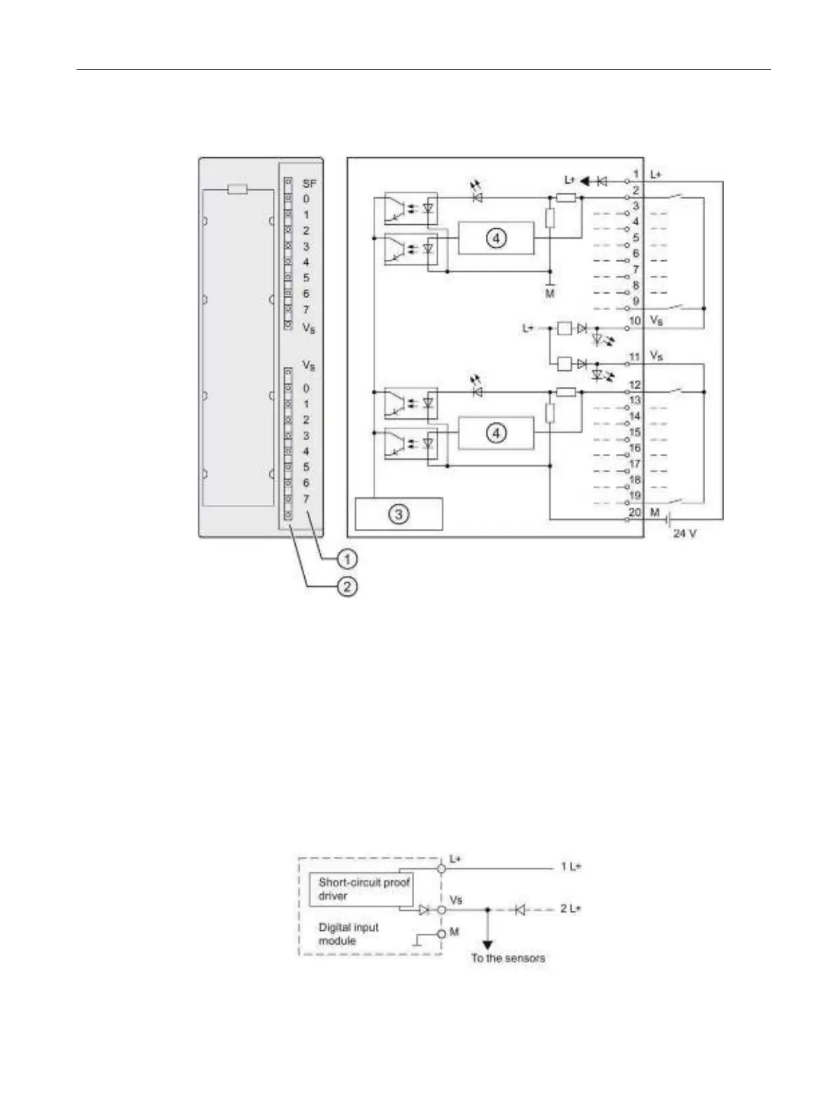
Wiring and block diagram of SM 321; DI 16 x DC 24 V
Channel number
Status displays - green
Error displays - red
Sensor supply V
S
-green
Backplane bus interface
Wire-break detection
Wiring diagram of the redundant sensor supply
The figure below shows how an additional redundant voltage source can be used to power
sensors using Vs.
Figure 3-4 Wiring diagram of the redundant supply of sensors of SM 321; DI 16 x DC 24 V

Table of Contents

Other manuals for Siemens SIMATIC

Questions and Answers:

Question and Answer IconNeed help?

Do you have a question about the Siemens SIMATIC and is the answer not in the manual?

Siemens SIMATIC Specifications

General IconGeneral
Product type designationSIMATIC
CPUVaries by model
MemoryVaries by model
Input/OutputVaries by model
CommunicationVaries by model
Programming LanguageSTEP 7
Operating Temperature0°C to 60°C (varies by model)
Protection ClassIP20
CategoryProgrammable Logic Controller (PLC)

Related product manuals