Digital modules
3.11 Digital input module SM 321; DI 16 x 24 VDC; with hardware and diagnostic interrupts (6ES7321-7BH01-
0AB0)
S7-300 Module data
84 Manual, 06/2017, A5E00105505-AJ
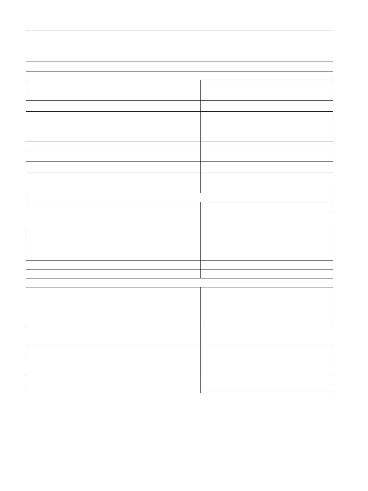
Status, interrupts, diagnostics
Status display
• Inputs
green LED per channel
• Sensor supplies (Vs)
green LED per output
Interrupts
• Hardware interrupt
• Diagnostic interrupt
programmable
programmable
• Group error display
red LED (SF)
• Reading diagnostic information
supported
Monitoring for
• wirebreak
yes, sensing I < 1 mA
Number of outputs 2
Output voltage
• on load
min. L+ (- 2.5 V)
Output current
• Rated value
• Permitted range
120 mA
0 mA to 150 mA
Additional (redundant) supply
Input voltage
• Rated value
• "1" signal
• "0" signal
24 V DC
13 V to 30 V
-30 V to + 5 V
Input current
• "1" signal
typ. 7 mA
Connection of 2-wire BEROs
• Permissible quiescent current
supported
max. 2 mA
Wiring of the signal transmitters
using a 20-pin front connector
Shunt circuit of the sensor for wire-break detection