Digital modules
3.11 Digital input module SM 321; DI 16 x 24 VDC; with hardware and diagnostic interrupts (6ES7321-7BH01-0AB0)
S7-300 Module data
Manual, 06/2017, A5E00105505-AJ
87
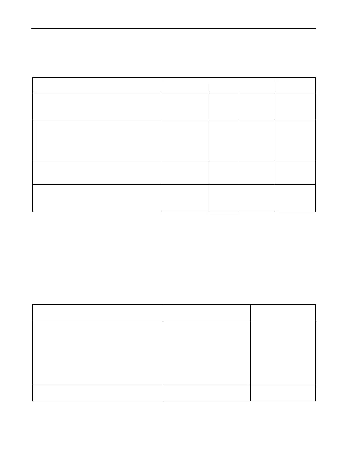
The default settings apply if you have not set any parameters in STEP 7.
Table 3- 10 Parameters of SM 321; DI 16 x DC 24 V
Enable
• Diagnostic interrupt
• Hardware interrupt
Yes/No
Yes/No
No
No
dynamic
Module
Input delay/voltage type 0.1 ms (DC)
0.5 ms (DC)
3 ms (DC)
15 ms (DC)
(DC) static Module
Diagnosis encoder supply missing
• Wire break
Yes/No
No
static
Channel group
Hardware interrupt trigger
• Positive edge
• Negative edge
Yes/No
Yes/No
No
No
dynamic
Channel group
Allocating the sensor supplies to channel groups
The module's two sensor supplies power the two channel groups: Inputs 0 to 7 and inputs 8
to 15. You also configure the diagnostics for the encoder supply in these channel groups.
Assigning interrupt parameters to channel groups
The table below shows which channels you can group for interrupt processing.
The channel group number is required to program SFC parameters in the user program.
Table 3- 11 Assigning interrupt parameters to the inputs of SM 321; DI 16 x DC 24 V
Programmable in the following
channel groups
• Hardware interrupt (triggered at the positive, nega-
tive, or both edges)
• Diagnostic interrupt for wire break
0 and 1
2 and 3
4 and 5
6 and 7
8 and 9
10 and 11
12 and 13
0
1
2
3
4
5
6
• Diagnostic interrupt for missing encoder supply
0 to 7
8 to 15
-