Digital modules
3.12 Digital input module SM 321; DI 16 x DC 24/125 V; with hardware and diagnostic interrupts (6ES7321-7EH00-0AB0)
S7-300 Module data
Manual, 06/2017, A5E00105505-AJ
95
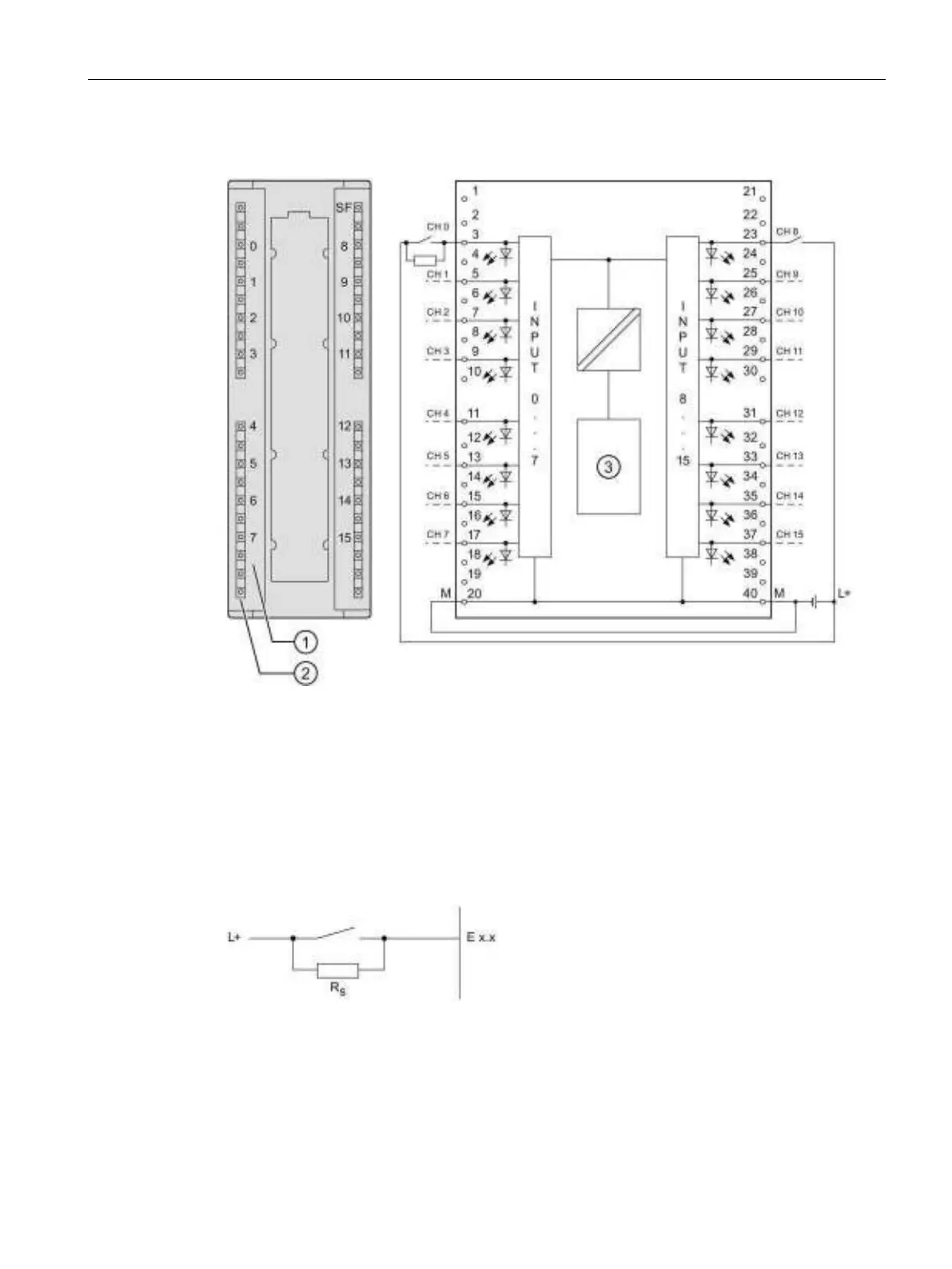
Wiring and block diagram of SM 321; DI 16 x DC 24 V/125 V
Status displays - green
Wiring diagram of the shunt circuit of the sensors
For wire-break detection, it is necessary to connect a shunt resistor to the transducer
contacts.
Figure 3-7 Wiring diagram of the shunt circuit of transducers of SM 321; DI 16 x DC 24 V/125 V