Direction of ro‐
tation
According to IEC According to NEMA
Line feeder cables - L1L2L3 L1L2L3
Terminal connec‐
tion
Clockwise ro‐
tation
UVW T1T2T3
Terminal connec‐
tion
Counter-clock‐
wise rotation
VUW T2T1T3
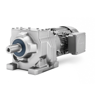
Direction of rotation of the motor when viewing the DE
6.1.4.3 Terminal marking
According to IEC / EN 60034‑8, the following basic denitions apply to the terminal markings for
3-phase machines:
Table 6-1 Terminal markings using the 1U1-1 as an example
1 U 1 - 1 Marking
x Code for split winding, where applicable. Special case for pole assignment for pole-
changing machines.
A lower index signies a lower speed.
x Phase designation U, V, W
x Index for winding start (1) or end (2) or if there is more than one connection per
winding
x Additional indices for cases in which it is obligatory to connect parallel power feed
cables to several terminals with otherwise identical markings
6.1.4.4 Additional bores in the terminal box
Additional bores in the terminal box must be drilled by the manufacturer or by a specialist
workshop for electrical machinery that has been authorized by the manufacturer.
6.1.4.5 Cable entry
Certied cable entries, thread adapters and sealing plugs
Only use sealing plugs, cable glands and conductor glands or thread adapters that are suitable,
certied and marked for use in the respective explosion protection type and degree of protection
(IEC / EN 60079-14) or the appropriate country regulations.
Terminal box
The number and size of the cable entry tapped holes is provided in the machine dimension
drawing.
Electrical connection
6.1Connecting the machine
1MB..1/2/3/4 - shaft heights 63 ... 355
Operating Instructions, 11/2023, A5E52779900A 81
 Loading...