CAUTION
Damage to connecting cables that are freely led out
You must observe the following note to avoid damaging connecting cables that are freely led
out:
• It must be ensured that there are no foreign bodies, dirt, or moisture in the terminal base
of the machine enclosure.
• Use O-rings or suitable at gaskets to seal entries in cover plates (DIN 42925) and other
open entries.
• Seal the terminal base of the machine enclosure using the original seal of the cover plate to
prevent dust and water from entering.
• Please observe the tightening torques for cable entries and other screws.
6.1.4.7 Connecting protruding cables
In the case of connection cables brought out of the machine, no terminal board is installed on
the terminal base of the machine housing. The connection cables are directly connected to
stator winding terminals at the factory.
The connection cables are color-coded or labeled. The customer directly connects individual
cables in the control cabinet for their system in accordance with the labeling.
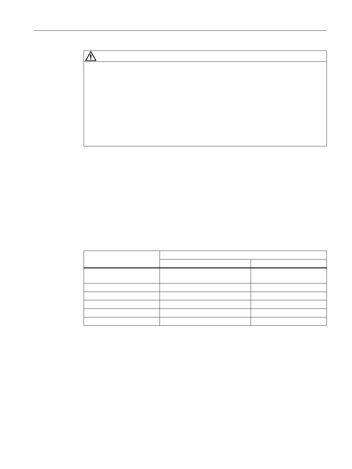
6.1.4.8 Thread sizes in the terminal box
Shaft height Threaded entry
Size Quantity
63 ... 90 M16x1.5
M25x1.5
1
100 ... 132 M32x1.5 2
160 ... 180 M40x1.5 2
200 ... 225 M50x1.5 2
250 ... 315 M63x1.5 2
355 M80x2 2
Thread size for additional glands, e.g. PTC thermistor or anti-condensation heating M16x1.5
or M20x1.5
Deviating thread sizes are specied at the motor.
6.1.4.9 Internal equipotential bonding
The internal equipotential bonding between the grounding terminal in the terminal box, the
terminal box components and the machine enclosure is ensured via metallic contact, a copper
braided strip or a stranded wire.
Electrical connection
6.1Connecting the machine
1MB..1/2/3/4 - shaft heights 63 ... 355
Operating Instructions, 11/2023, A5E52779900A 83
 Loading...