5.11.2 Setting the filter for fail-safe digital inputs
You must set the input filter and the simultaneity monitoring of the fail-safe digital input for all
SINAMICS inverters, where the fail-safe digital input F‑DI evaluates two redundant signals.
For SIMATIC ET 200pro FC-2, the input signal for STO is received from the F0 rail of the
backplane bus of the ET200pro system. This is the reason that the SIMATIC ET 200pro FC‑2
inverter has no simultaneity monitoring.
Requirement
You are online with STARTER or Startdrive online.
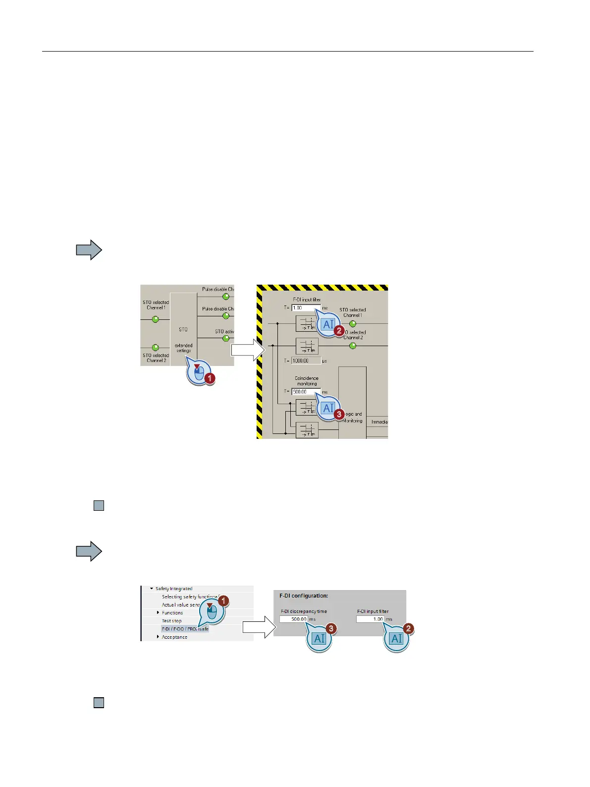
Procedure with STARTER
Proceed as follows to set the input filter and the simultaneity monitoring of the fail-safe digital
input:
1. Select the "Extended settings" button.
2. Set the debounce time for the F-DI input filter.
3. Set the discrepancy time for the simultaneity monitoring.
4. Close the screen form.
You have set the input filter and the simultaneity monitoring of the fail-safe digital input.
Procedure with Startdrive
Proceed as follows to set the input filter and the simultaneity monitoring of the fail-safe digital
input:
1. Navigate to the filter settings.
2. Set the debounce time for the F-DI input filter.
3. Set the discrepancy time for the simultaneity monitoring.
You have set the input filter and the simultaneity monitoring of the fail-safe digital input.
Commissioning
5.11 Setting basic functions
Safety Integrated - SINAMICS G110M, G120, G120C, G120D and SIMATIC ET 200pro FC-2
128 Function Manual, 01/2017, FW V4.7 SP6, A5E34261271B AD

 Loading...


