4.4.3.2 SIRIUS 3SK1 safety relay
The typical wiring examples subsequently described are based on safety relays with relay
enable circuits. Safety relays with semiconductor enable circuits can also be used.
The diagrams only show how the safety relay and inverter are interconnected.
You will find additional information about the safety related on the Internet:
SIRIUS 3SK1 safety relays (
https://support.industry.siemens.com/cs/ww/en/ps/16381/man)
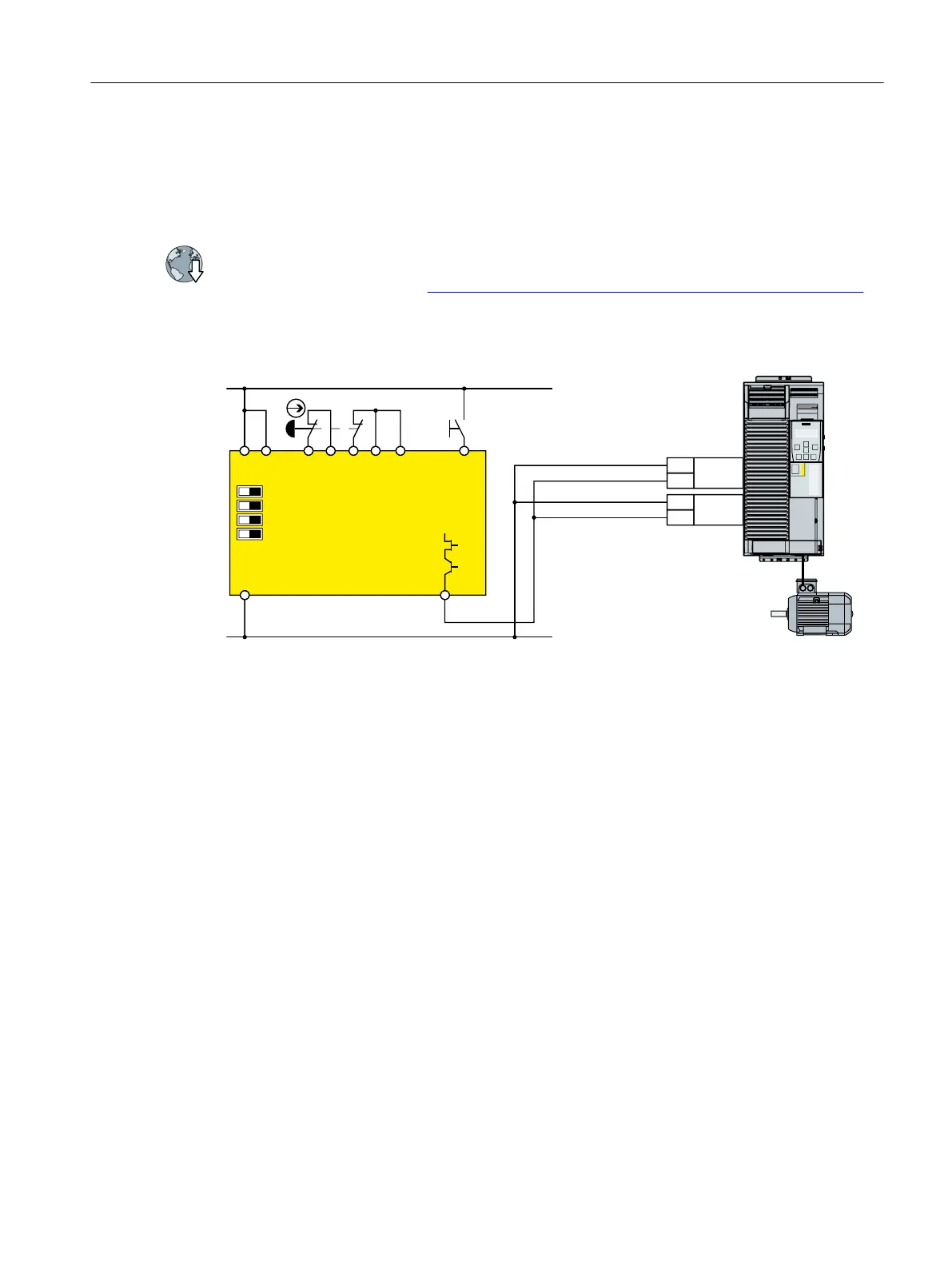
Components in the same control cabinet
9'&
6WDUW
0
672B$
672B%
9
9
9
9
6.$%
$4
$,1.,1),1,167,17
$XWRVWDUW0RQLWRUHG6WDUW
&URVVIDXOWGHWHFWLRQ2))21
VLQJOHFKDQQHOVGRXEOHVHQVRU
6WDUWXSWHVW\HVQR
6,1$0,&6*
3RZHU0RGXOH30
303
Figure 4-35 Wiring the inverter and safety relay within a control cabinet
A control cabinet that has been designed and wired correctly does not contain any damaged
wiring or cross circuits.
Under the assumption that the upstream, preprocessing device switches the output being used
twice, within a control cabinet, you can wire up the safety relay and the inverter through a
single-channel cable connection. At the inverter, you must connect both terminals of the fail-
safe digital input with one another.
Installing
4.4 Controlling via a fail-safe digital input
Safety Integrated - SINAMICS G110M, G120, G120C, G120D and SIMATIC ET 200pro FC-2
Function Manual, 01/2017, FW V4.7 SP6, A5E34261271B AD 87

 Loading...


