6.9 Response to a discrepancy in the signals transferred via PROFIsafe
Drive response
7HOHJUDP
7ROHUDQFHWLPH
GLVFUHSDQF\
*UHHQ
RQ
*UHHQ
RQ
5HGIODVKHVUDSLGO\
<HOORZRQ
6DIHW\LQSXWHJ
)',
)DLOVDIHDFNQRZO
HGJPHQW
6WDQGDUG
DFNQRZOHGJPHQW
6B=6:
)&38
352),1(7352),VDIH
)',
)',
)',
W
W
/('5'<
/('6$)(
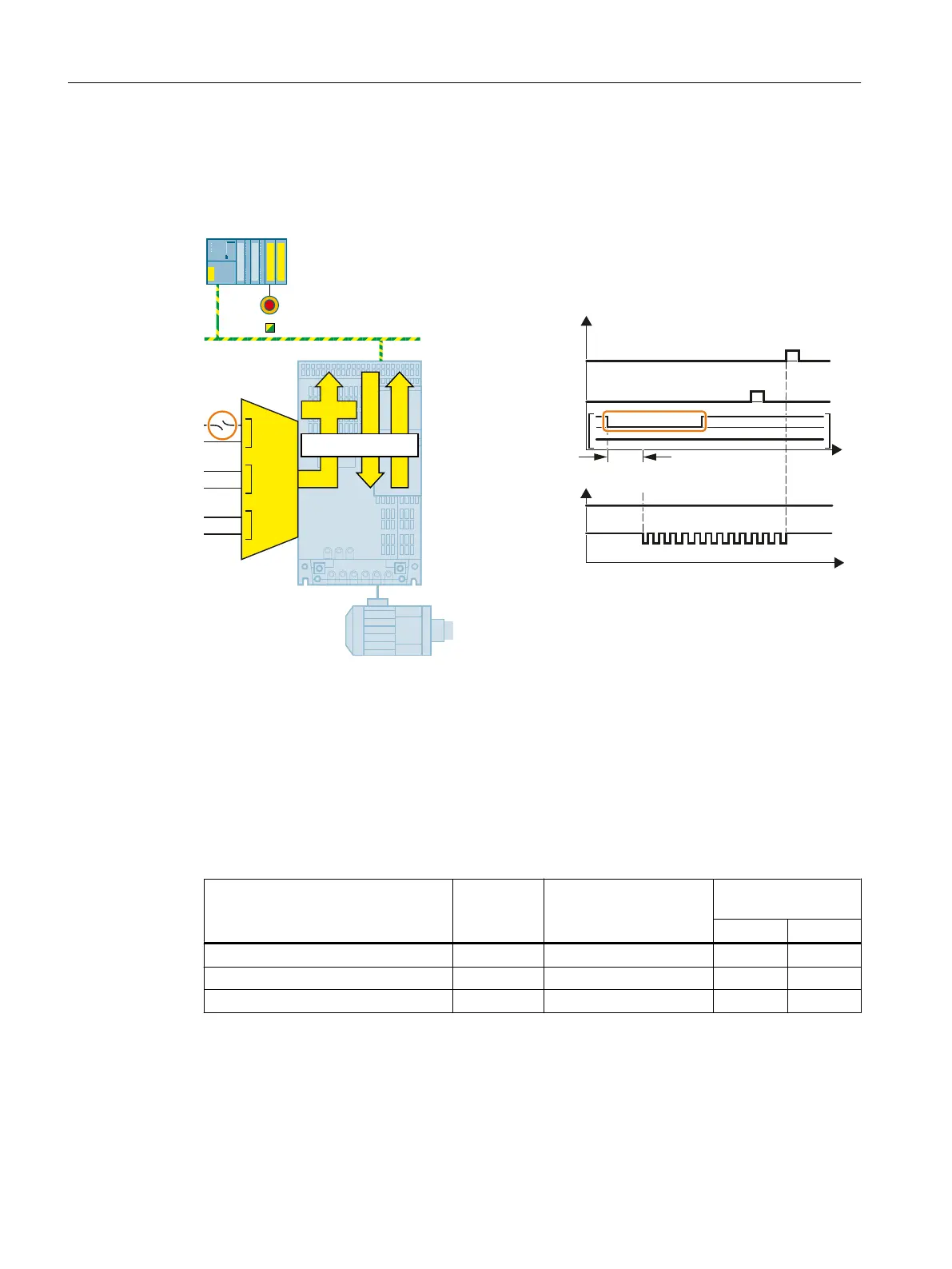
Figure 6-49 Behavior of the inverter in the event of a discrepancy in a fail-safe digital input in PROFIsafe
telegram 900
The inverter does not set the error bit of the safety functions (= internal event).
After the tolerance time has expired, the inverter signals the discrepancy (fault C01770 or
C30770).
Independent of the voltage levels available, the inverter sets the evaluation of the discrepant
fail-safe digital input into the safe state (= zero) until you acknowledge the inverter using a fail-
safe signal or you switch off the power supply voltage and switch it on again.
Inverter signals Parameter Included in the PROFI‐
safe telegram
Can be interconnec‐
ted with
F-DI F-DO
Internal event r9722.7 ✓ --- ✓
"Standard" acknowledgment p2103 --- --- ---
Fail-safe acknowledgment r9720.7 ✓ ✓ ---
Operation
6.9 Response to a discrepancy in the signals transferred via PROFIsafe
Safety Integrated - SINAMICS G110M, G120, G120C, G120D and SIMATIC ET 200pro FC-2
292 Function Manual, 01/2017, FW V4.7 SP6, A5E34261271B AD

 Loading...


