EasyManuals Logo

Siemens SINAMICS G120C Function Manual

Siemens SINAMICS G120C
450 pages
To Next Page IconTo Next Page
To Previous Page IconTo Previous Page
Page #236 background imageLoading...
Page #236 background image
6.4.2 Response to faults in the brake control
Faults in the brake control
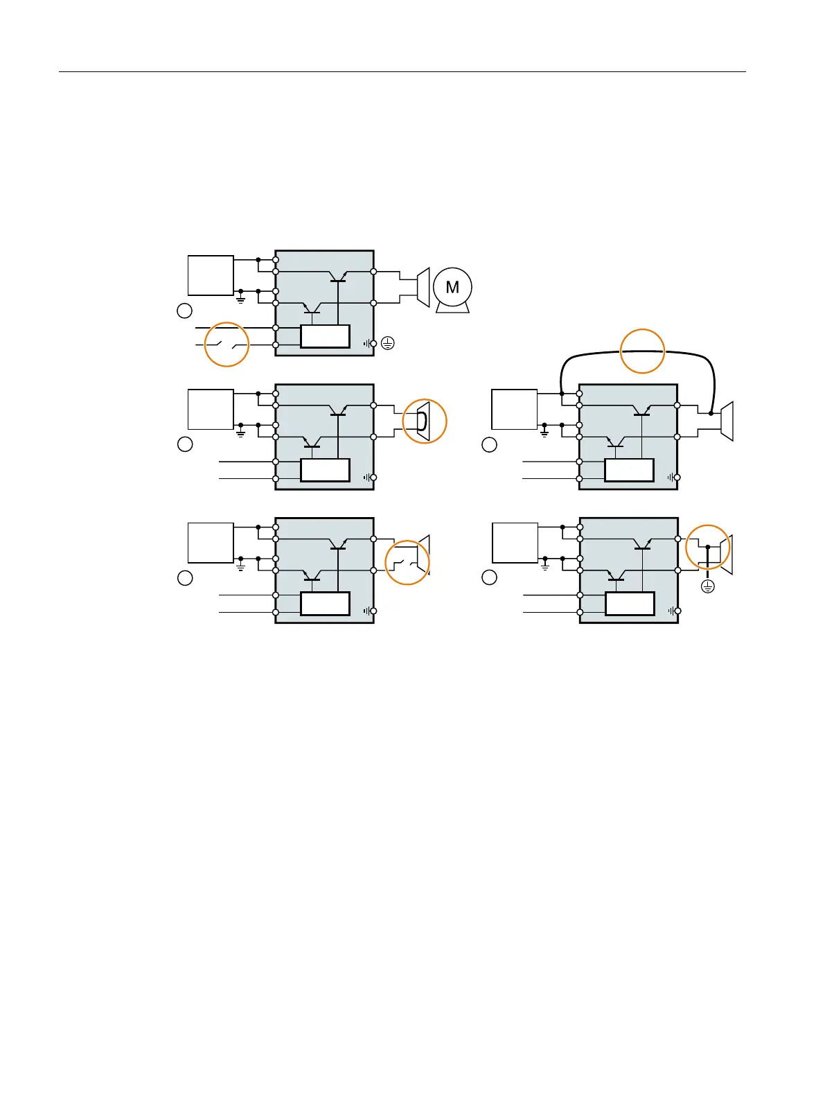
When opening or closing the brake, the inverter identifies faults in the brake cable and in the
brake winding.
'&b9
6DIH%UDNH5HOD\
%5
%5
&75/
0
0
Control cable from the inverter to the Safe Brake Relay is interrupted
Short-circuit in the brake winding
Cross circuit between the brake cable and the 24 V supply voltage
Brake cable is interrupted
Ground fault on the brake cable
Figure 6-16 Examples of faults in the brake control
Drive response
If the inverter detects a fault in the brake control, it responds with a STOP A (message F01630
or F30630) and closes the brake.
Operation
6.4 Safe Brake Control (SBC)
Safety Integrated - SINAMICS G110M, G120, G120C, G120D and SIMATIC ET 200pro FC-2
236 Function Manual, 01/2017, FW V4.7 SP6, A5E34261271B AD

Table of Contents

Other manuals for Siemens SINAMICS G120C

Questions and Answers:

Question and Answer IconNeed help?

Do you have a question about the Siemens SINAMICS G120C and is the answer not in the manual?

Siemens SINAMICS G120C Specifications

General IconGeneral
Communication InterfacesPROFINET, PROFIBUS, USS, Modbus RTU
Protection ClassIP20
Ambient Temperature-10°C to +50°C
Storage Temperature-40°C to +70°C
Power Range0.55 kW to 132 kW
Voltage Range380 V to 480 V
Output Voltage0 V to Supply Voltage
Frequency Range0 Hz to rated output frequency
Control ModesVector control with encoder
ProtectionOverload, overvoltage, undervoltage, short circuit, ground fault
Relative Humidity5% to 95%, non-condensing
AltitudeUp to 2000 m without derating

Related product manuals