6.2.5 Testing a fail-safe digital output
Time of the test
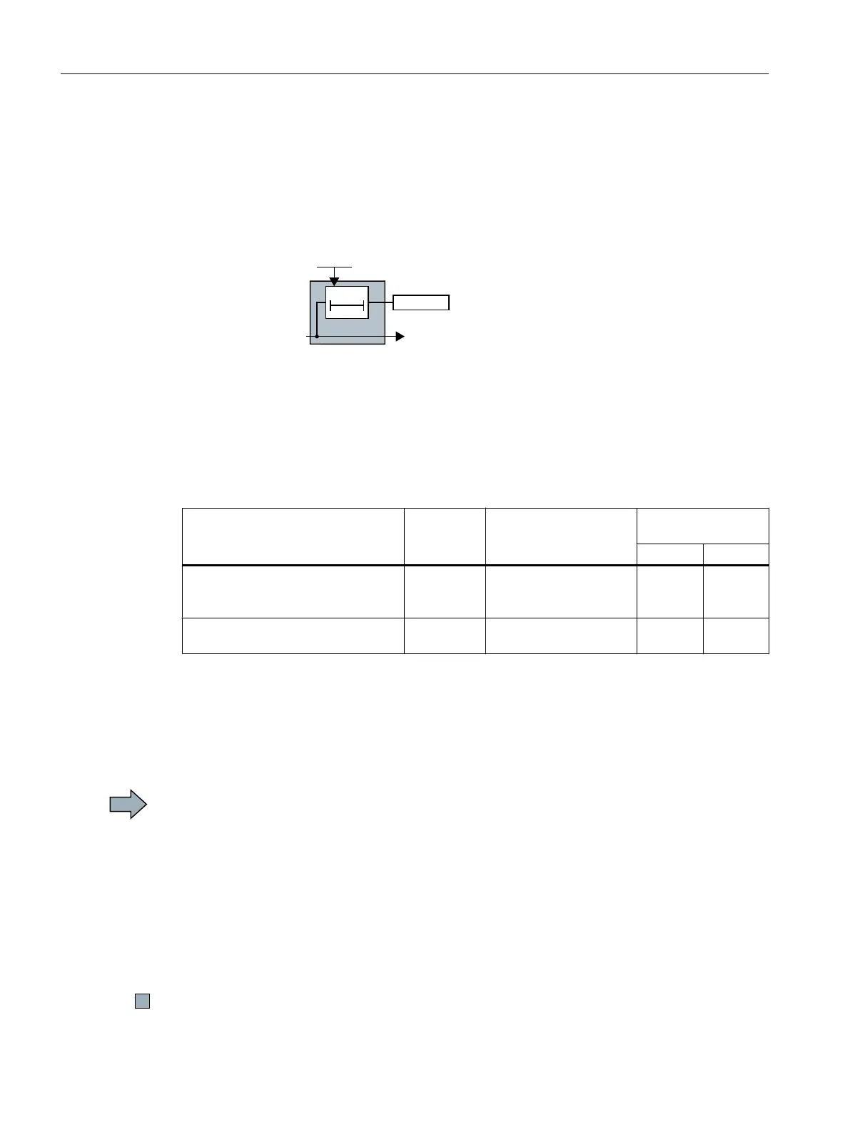
The inverter monitors that the test is regularly performed using a time block.
6WDUWIRUFHGFKHFNLQJ
SURFHGXUH
0RQLWRULQJWLPHIRUIDLOVDIHGLJLWDO
RXWSXW
7HVWVWRSUHTXLUHGIRUWKHGLJLWDORXWSXWV
6WDUWIRUFHGFKHFNLQJSURFHGXUHRIWKHIDLOVDIH
RXWSXW
$
7
Figure 6-4 Start and monitoring of the forced checking procedure (test stop) of the fail-safe digital
output
If the inverter outputs alarm A01774, you must initiate the test at the next opportunity, e.g.:
● When the system is switched on.
● At specified regular intervals before the monitoring time expires.
Inverter signals Parameter Included in the PROFI‐
safe telegram
Can be interconnec‐
ted with
F-DI F-DO
Forced checking procedure (test
stop) required for the extended func‐
tions
r9723.0 --- --- ---
Start forced checking procedure (test
stop) of the fail-safe digital output
p10007 --- --- ---
Testing the fail-safe digital output and the connected actuator
The inverter tests its fail-safe digital output and the connected actuator for a signal change at
the fail-safe digital output.
Procedure
To test the fail-safe digital output, proceed as follows:
1. Switch on the motor (ON/OFF1 command = 1).
If you wish to carry out the forced checking procedure at standstill, the speed setpoint must
be = 0.
2. Start the test using a signal of your choice, for example a digital input.
3. The inverter briefly switches off the fail-safe digital output. This test takes several
milliseconds.
4. Set the signal to start the forced checking procedure to zero.
5. Check that alarm A01774 is no longer present.
You have tested the fail-safe digital output.
Operation
6.2 Regularly testing the safety functions
Safety Integrated - SINAMICS G110M, G120, G120C, G120D and SIMATIC ET 200pro FC-2
220 Function Manual, 01/2017, FW V4.7 SP6, A5E34261271B AD

 Loading...


