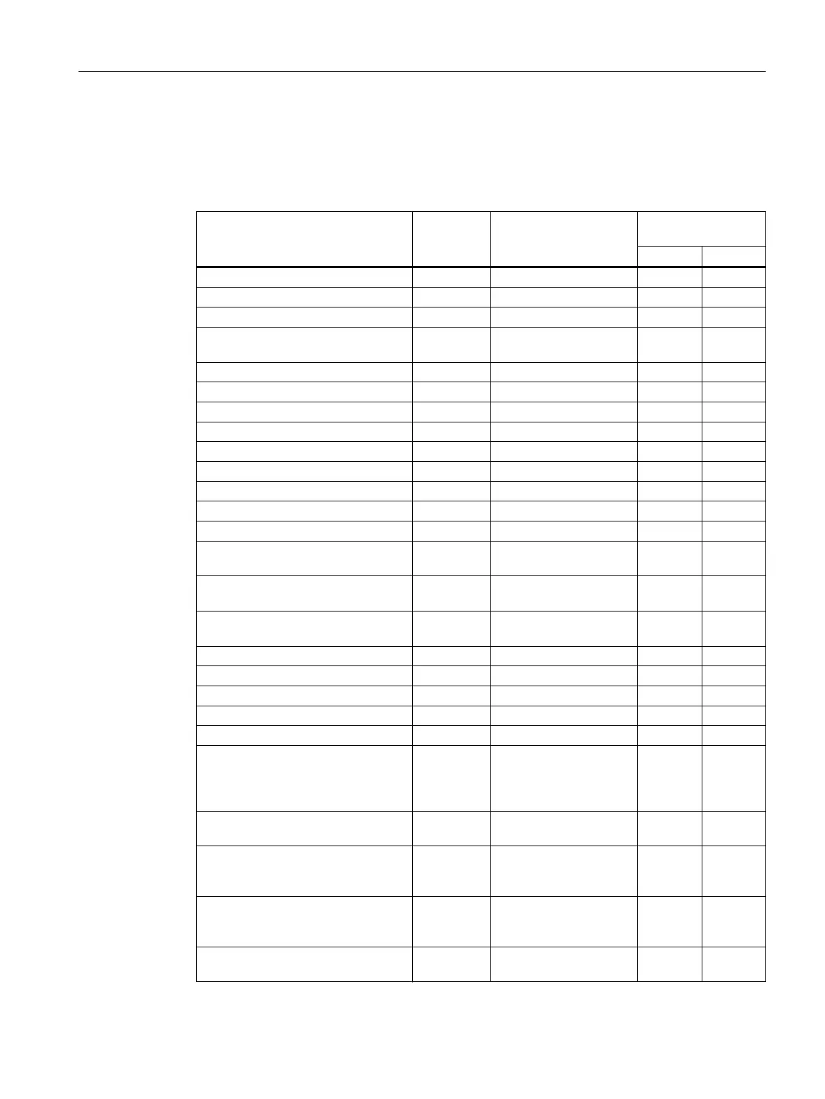
6.13 Overview of the inverter signals relevant for operation
The following table lists the signals relevant for using the safety functions: Most of the signals
are included in the PROFIsafe telegram, or can be interconnected using a fail-safe input or
output.
Inverter signals Parameter Included in the PROFI‐
safe telegram
Can be interconnec‐
ted with
F-DI F-DO
Internal event r9722.7 ✓ --- ✓
STO active (basic functions) r9773.1 ✓ --- ✓
STO deselection (basic functions) r9773.0 ✓ ✓ ---
STO cause, selection via terminal on
the Power Module
r9772.25 --- --- ---
STO active (extended functions) r9722.0 ✓ --- ✓
Deselect STO (extended functions) r9720.0 ✓ ✓ ---
SBC requested (basic functions) r9773.4 --- --- ---
SS1 active (basic functions) r9773.6 ✓ --- ✓
Deselect SS1 (basic functions) r9773.5 ✓ ✓ ---
SS1 active (extended functions) r9722.1 ✓ --- ✓
Deselect SS1 (extended functions) r9720.1 ✓ ✓ ---
SLS active r9722.4 ✓ --- ✓
Deselect SLS r9720.4 ✓ ✓ ---
SLS level active r9722.9,
r9722.10
✓ --- ✓
Select SLS level r9720.9,
r9720.10
✓ ✓ ---
SSM feedback signal active (speed
below limit value)
r9722.15 ✓ --- ✓
SDI+ active r9722.12 ✓ --- ✓
SDI+ deselect r9720.12 ✓ ✓ ---
SDI- active r9722.13 ✓ --- ✓
Deselect SDI- r9720.13 ✓ ✓ ---
SAM/SBR active r9723.16 --- --- ---
Forced checking procedure (test
stop) of the STO terminals on the
PM240-2 or PM240P‑2 Power Mod‐
ule required
r9773.30 --- --- ---
Forced checking procedure (test
stop) required for the basic functions
r9773.31 --- --- ---
Forced checking procedure (test
stop) required for the extended func‐
tions
r9723.0 --- --- ---
Forced checking procedure (test
stop) required for the extended func‐
tions
p9705 --- --- ---
Start forced checking procedure (test
stop) of the fail-safe digital output
p10007 --- --- ---
Operation
6.13 Overview of the inverter signals relevant for operation
Safety Integrated - SINAMICS G110M, G120, G120C, G120D and SIMATIC ET 200pro FC-2
Function Manual, 01/2017, FW V4.7 SP6, A5E34261271B AD 317

 Loading...


