4.5 Evaluating via a fail-safe digital output
4.5.1 Overview
In the factory setting of the inverter, the fail-safe digital output is assigned to none of the
integrated safety functions. Only when commissioning do you define whether you use, for
example, the two digital outputs for standard functions, or you combine them to create a fail-
safe digital output.
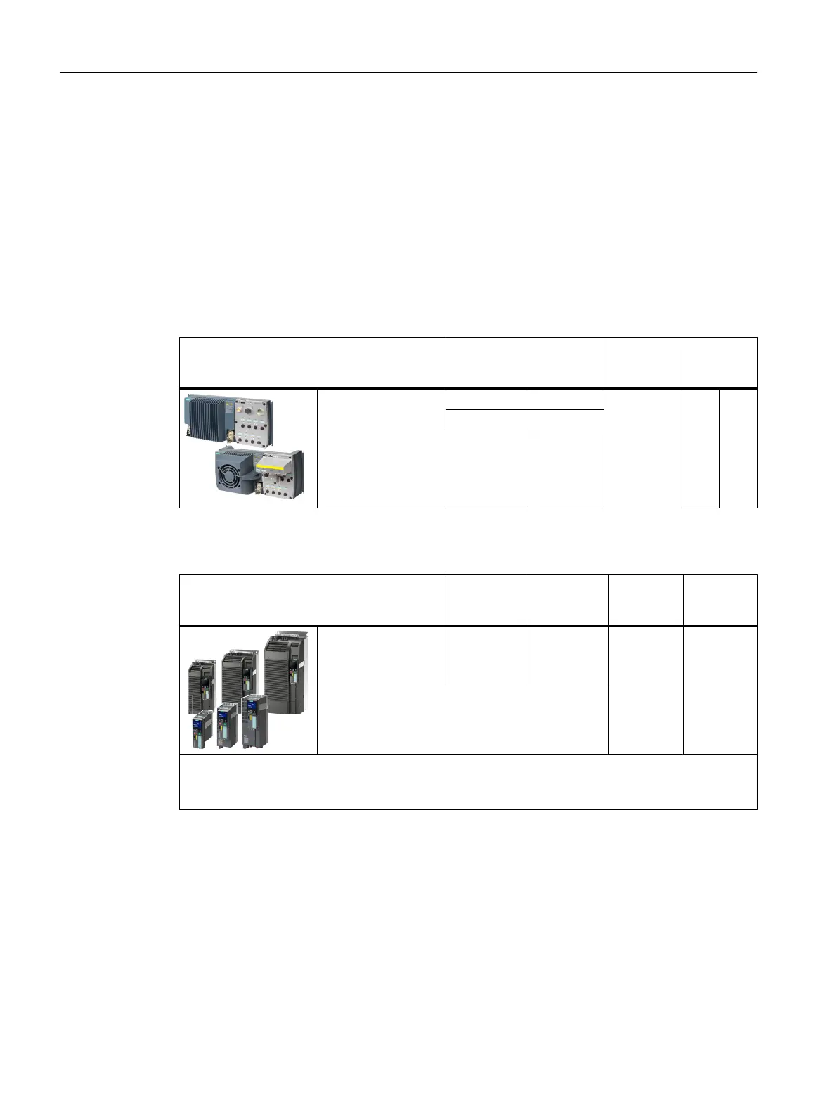
Table 4-17 inverters for cabinet-free installation (IP65)
SINAMICS G120D with Control Unit Connector.
Pin
Digital out‐
put
Fail-safe
digital out‐
put
Read back
input
CU240D‑2 DP‑F
CU240D‑2 PN‑F
CU240D‑2 PN‑F PP
CU250D‑2 DP‑F
CU250D‑2 PN‑F
CU250D‑2 PN‑F PP
X5.4 DO 0 F-DO 0 X9.2 DI 5
X5.2 DO 1
X5.3 2M
Table 4-18 Inverter for installation in a control cabinet (IP20)
SINAMICS G120 with Control Unit Terminal
strip
Digital out‐
put
Fail-safe
digital out‐
put
Read back
input
CU250S‑2
CU250S‑2 DP
CU250S-2 PN
CU250S‑2 CAN
18: NC
19: NO
20: COM
DO 0 F-DO 0 67 DI 6
23: NC
24: NO
25: COM
DO 2
Most applications require NO contacts for the fail-safe digital output.
If your application requires it, instead of NO contacts, you can also use the two NC contacts of the
inverter. The safe state of the fail-safe digital output is always the quiescent state of the two relays.
What devices can be connected?
The fail-safe digital output is designed for the following devices:
● Direct connection of a fail-safe digital input.
● Connection of two relays.
Installing
4.5 Evaluating via a fail-safe digital output
Safety Integrated - SINAMICS G110M, G120, G120C, G120D and SIMATIC ET 200pro FC-2
94 Function Manual, 01/2017, FW V4.7 SP6, A5E34261271B AD

 Loading...


