4.4.3.3 3RK3 Modular Safety System
You can use the following outputs to control the fail-safe digital inputs in the inverter:
● The fail-safe digital outputs in the central modules of the modular 3RK3 safety system
● The fail-safe digital outputs in the EM 2/4F-DI 2F-DO expansion module.
● The fail-safe digital outputs in the EM 4F-DO expansion module.
● The fail-safe relay outputs in the EM 4/8F-RO expansion module
● Two individual relay contacts of the EM 2/4F-DI 1/2F-RO expansion module.
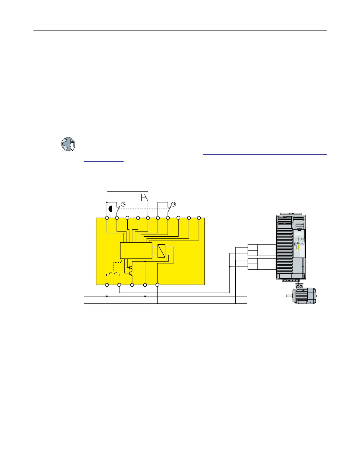
The diagrams only show the wiring between the modular 3RK3 safety system and the inverter.
You can find additional information on the modular 3RK3 safety system in the Internet:
SIRIUS 3RK3 modular safety system manual (
https://support.industry.siemens.com/cs/ww/en/
view/26493228)
Components in the same control cabinet
/RJLF
6WDUW
5.
$$
444/0
7
,1,1,1,17
,1,1,1,1
9'&
0
672B$
672B%
9
9
9
9
6,1$0,&6*
3RZHU0RGXOH30
303
Figure 4-37 Wiring inverters and modular safety system within one control cabinet
A control cabinet that has been designed and wired correctly does not contain any damaged
wiring or cross circuits.
In the upstream, preprocessing device, if you only use outputs with two switches in series,
then you may wire the safety relay to the inverter via a single-channel cable connection. At the
inverter, you must connect both terminals of the fail-safe digital input with one another.
Installing
4.4 Controlling via a fail-safe digital input
Safety Integrated - SINAMICS G110M, G120, G120C, G120D and SIMATIC ET 200pro FC-2
Function Manual, 01/2017, FW V4.7 SP6, A5E34261271B AD 89

 Loading...


