EasyManuals Logo

Siemens SINAMICS G120C Function Manual

Siemens SINAMICS G120C
450 pages
To Next Page IconTo Next Page
To Previous Page IconTo Previous Page
Page #143 background imageLoading...
Page #143 background image
3. Remove the interconnection of the digital input that you use as feedback signal input for
the fail-safe digital output:
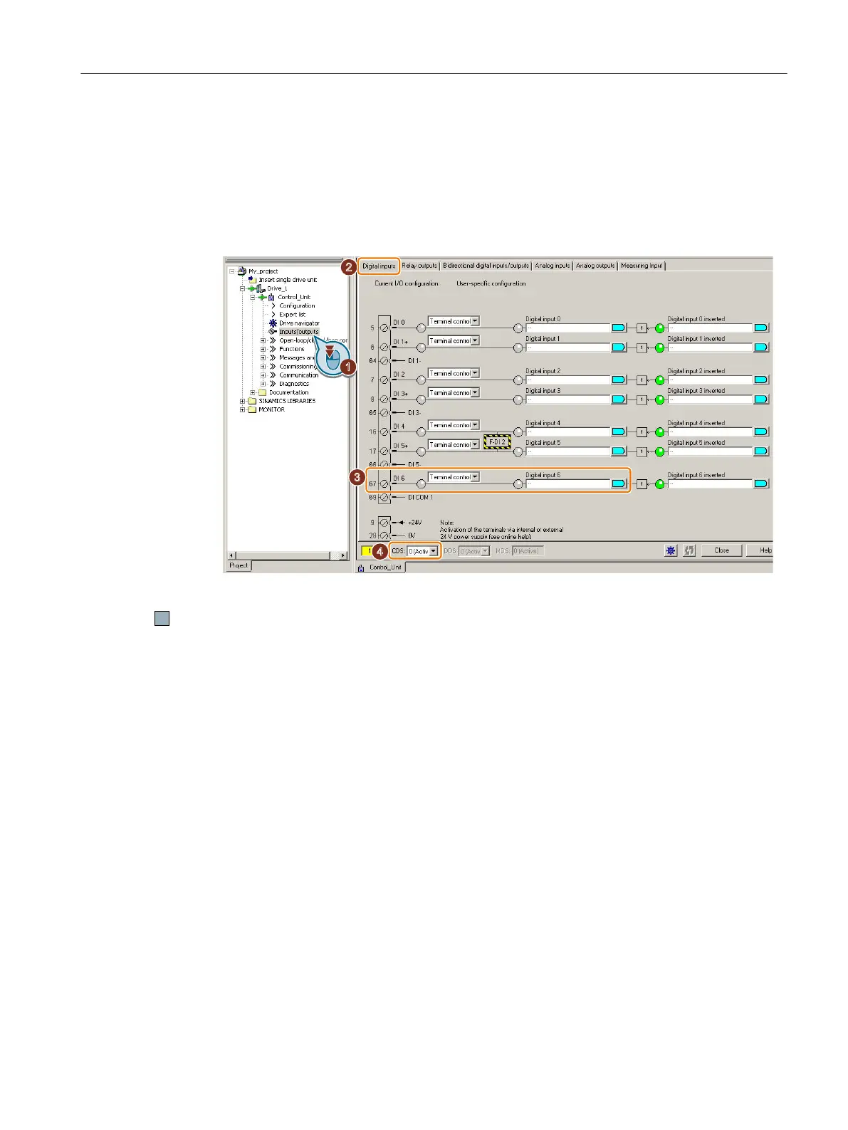
SINAMICS G120 with CU250S-2 Control Unit: Digital input DI 6 (see diagram).
SINAMICS G120D: Digital input DI 5.
4. If you use the CDS data set switchover, remove the interconnection of the feedback signal
input for all CDS.
Figure 5-10 Removing the interconnection of the feedback signal input DI 6 for the CU250S-2
You have now prevented that the feedback signal input of the fail-safe digital output controls
"standard" functions in the inverter.
Commissioning
5.11 Setting basic functions
Safety Integrated - SINAMICS G110M, G120, G120C, G120D and SIMATIC ET 200pro FC-2
Function Manual, 01/2017, FW V4.7 SP6, A5E34261271B AD 143

Table of Contents

Other manuals for Siemens SINAMICS G120C

Questions and Answers:

Question and Answer IconNeed help?

Do you have a question about the Siemens SINAMICS G120C and is the answer not in the manual?

Siemens SINAMICS G120C Specifications

General IconGeneral
Communication InterfacesPROFINET, PROFIBUS, USS, Modbus RTU
Protection ClassIP20
Ambient Temperature-10°C to +50°C
Storage Temperature-40°C to +70°C
Power Range0.55 kW to 132 kW
Voltage Range380 V to 480 V
Output Voltage0 V to Supply Voltage
Frequency Range0 Hz to rated output frequency
Control ModesVector control with encoder
ProtectionOverload, overvoltage, undervoltage, short circuit, ground fault
Relative Humidity5% to 95%, non-condensing
AltitudeUp to 2000 m without derating

Related product manuals