3. Interconnect this signal, for example with a digital input or a control bit in the fieldbus. This
signal starts the forced checking procedure (test stop) of the fail-safe digital output - and
resets the remaining time of the monitoring to the value ④.
We recommend that the safety-related output is tested together with the forced checking
procedure of the safety functions. To do this, interconnect the signal source with the same
signal as the forced checking procedure of the safety functions.
Setting the forced dormant error detection (test stop) (Page 147)
4. Set the monitoring time for the forced checking procedure.
The time must be longer than or equal to the time for monitoring the forced checking
procedure of the extended functions.
Setting the forced dormant error detection (test stop) (Page 147)
5. Close the two screen forms.
You have defined which signal the inverter uses to start the forced checking procedure (test
stop) of its fail-safe digital output.
Procedure with Startdrive
To set the forced checking procedure (test stop) of the fail-safe digital output, proceed as
follows:
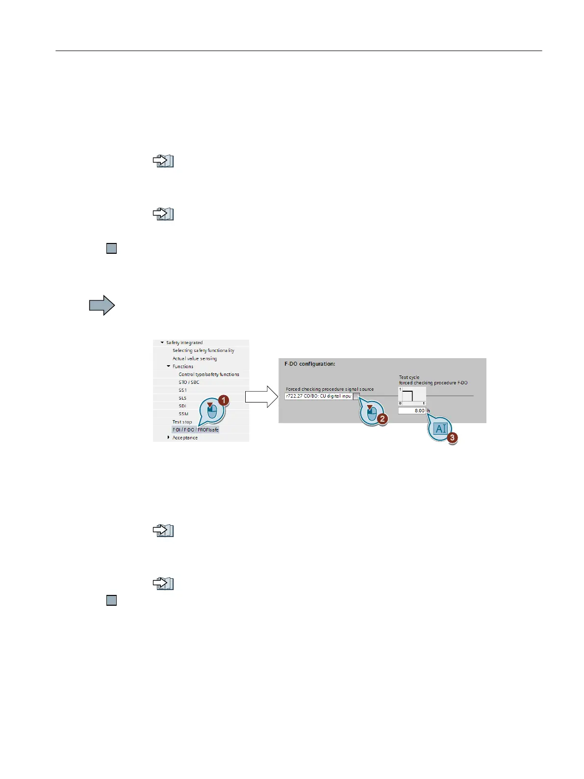
1. Select "F-DI / F-DO / PROFIsafe".
2. Interconnect this signal, for example with a digital input or a control bit in the fieldbus. This
signal starts the forced checking procedure (test stop) of the fail-safe digital output - and
resets the remaining time of the monitoring to the value ③.
We recommend that the fail-safe digital output is tested together with the forced checking
procedure of the safety functions. To do this, interconnect the signal source with the same
signal as the forced checking procedure of the safety functions.
Setting the forced dormant error detection (test stop) (Page 147)
3. Set the monitoring time for the forced checking procedure.
The time must be longer than or equal to the time for monitoring the forced checking
procedure of the extended functions.
Setting the forced dormant error detection (test stop) (Page 147)
You have defined which signal the inverter uses to start the forced checking procedure (test
stop) of its fail-safe digital output.
Description: Forced checking procedure of the fail-safe output
The forced checking procedure of the fail-safe digital output is the regular self-test of the
inverter, where the inverter checks whether the output can be shut down (deactivated).
Commissioning
5.12 Setting extended functions
Safety Integrated - SINAMICS G110M, G120, G120C, G120D and SIMATIC ET 200pro FC-2
Function Manual, 01/2017, FW V4.7 SP6, A5E34261271B AD 167

 Loading...


