6. Adjust the wait time. The following lower limits apply for the setting:
– The wait time must be longer than the response time t
R
of the connected actuator.
– The wait time must be longer than or equal to 24 ms.
– The wait time must be longer than the time for the input filter of the feedback input
(p10017).
Setting the filter for fail-safe digital inputs (Page 157)
7. Close the screen forms.
You have defined which signal the inverter transfers via its fail-safe digital output, and how the
inverter tests its fail-safe digital output.
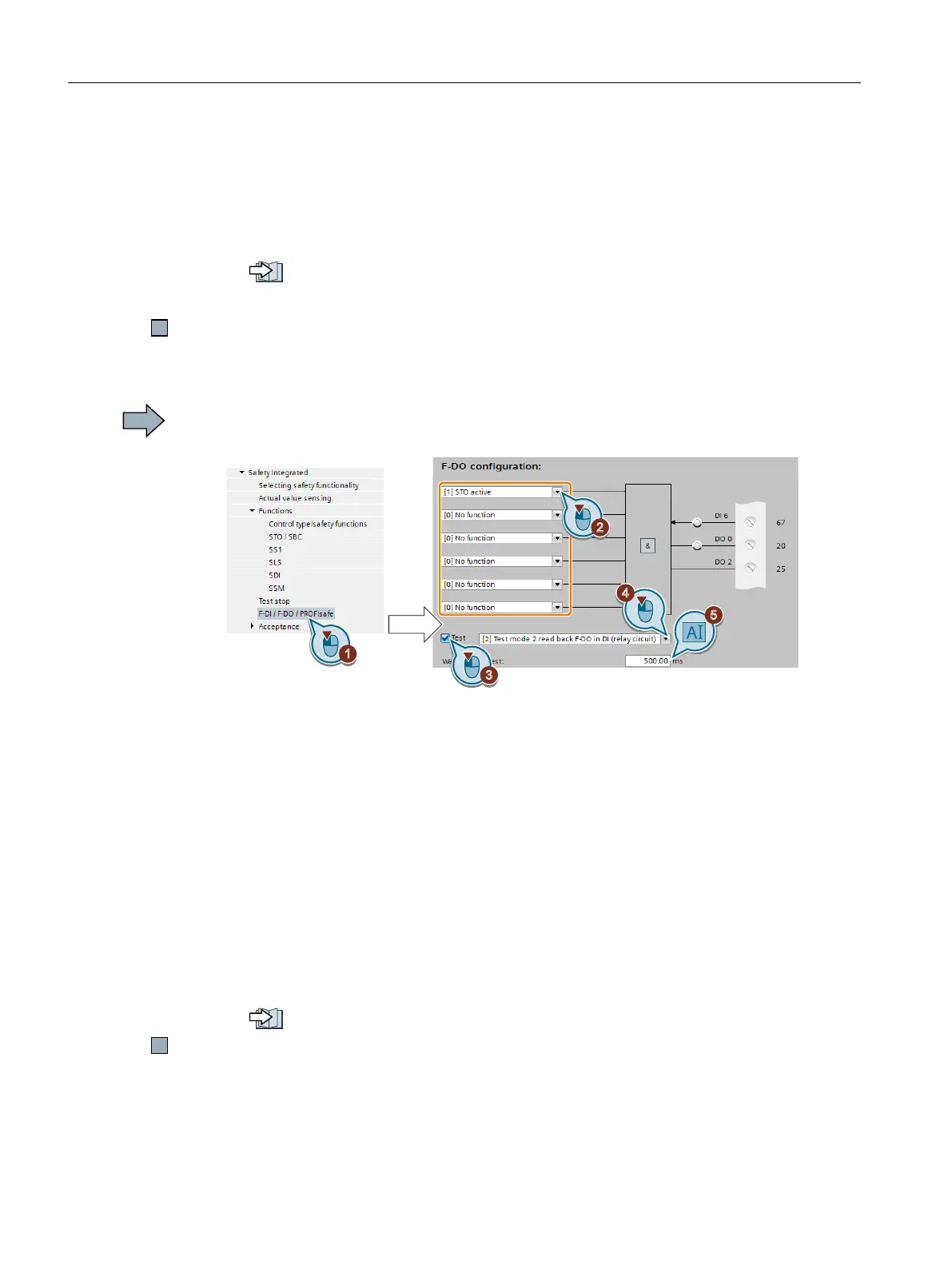
Procedure with Startdrive
To set the fail-safe digital output, proceed as follows:
1. Select "F-DI / F-DO / PROFIsafe".
2. Interconnect the status signals of your choice with the fail-safe digital output. The
"Safestate"signal is described below.
The inverter logically combines the status signals according to the following rules:
– The inverter ignored inputs without interconnection.
– If none of the inputs is interconnected, then the output signal = 0.
3. Activate the test for the fail-safe digital output.
4. Select the test mode that is compatible with your application.
5. Adjust the wait time. The following lower limits apply for the setting:
– The wait time must be longer than the response time t
R
of the connected actuator.
– The wait time must be longer than or equal to 24 ms.
– The wait time must be longer than the time for the input filter of the feedback input
(p10017).
Setting the filter for fail-safe digital inputs (Page 157)
You have defined which signal the inverter transfers via its fail-safe digital output, and how the
inverter tests its fail-safe digital output.
Commissioning
5.12 Setting extended functions
Safety Integrated - SINAMICS G110M, G120, G120C, G120D and SIMATIC ET 200pro FC-2
170 Function Manual, 01/2017, FW V4.7 SP6, A5E34261271B AD

 Loading...


