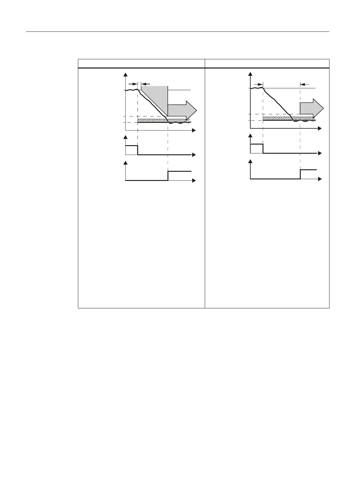
With braking ramp monitoring Without braking ramp monitoring
6SHHG
'HOD\WLPHIRUEUDNLQJ
UDPS
/LPLWDWLRQ
0RQLWRULQJ
6HWSRLQW
'HVHOHFW6/6
)',RU
352),VDIHFRQWURO
ZRUG
6/6DFWLYH
)'2RU
352),VDIHVWDWXV
ZRUG
6%5
W
W
W
6/6
After the adjustable "Delay time for braking ramp"
has elapsed, the inverter uses the SBR (Safe
Brake Ramp) function to determine whether the
speed has decreased.
The inverter switches from SBR to SLS as soon as
one of the following two conditions is fulfilled:
● The SBR monitoring ramp has reached the
value of the speed monitoring.
This case is shown in the diagram above.
● The actual load speed reaches the value of the
speed monitoring and the "delay time for
braking ramp" has expired.
Advantage:
● Already during braking, the inverter detects as
to whether the load speed decreases too slowly.
'HOD\WLPHDIWHU6/6
VHOHFWLRQ
6SHHG
/LPLWDWLRQ
6HWSRLQW
'HVHOHFW6/6
)',RU
352),VDIHFRQWURO
ZRUG
6/6DFWLYH
)'2RU
352),VDIHVWDWXV
ZRUG
0RQLWRULQJ
W
W
W
6/6
The inverter monitors the load speed after an ad‐
justable delay time has expired.
Advantage:
● Instead of the SBR subfunction, you must only
set the delay time.
Operation
6.6 Safely Limited Speed (SLS)
Safety Integrated - SINAMICS G110M, G120, G120C, G120D and SIMATIC ET 200pro FC-2
254 Function Manual, 01/2017, FW V4.7 SP6, A5E34261271B AD

 Loading...


