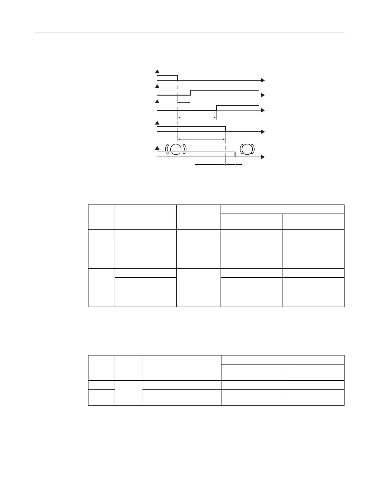
Response times when selected via a fail-safe digital input
00
672UHVSRQVH
WLPH
6LJQDOWRVHOHFW672
6HOHFW672
672LVDFWLYH
2XWSXW
6%&UHVSRQVHWLPH
0RWRUKROGLQJEUDNHLVWRSHQ
%UDNHFORVLQJ
WLPH
6DIH%UDNH5HOD\
WB(
W
W
W
W
W
Figure 8-2 Response times when selected via a fail-safe digital input
Table 8-4 Response times when using the basic functions
Function Selection via Response Response time
Worst case for a fault-
free inverter
Worst case for an inver‐
ter fault
STO F-DI STO is active 4 ms + t_E
1)
6 ms + t_E
1)
Terminals STO_A,
STO_B on the
PM240‑2 or PM240P‑2
Power Module.
20 ms ---
SBC F-DI Signal change
at the output of
the Safe Brake
Relay
8 ms + t_E
1)
22 ms + t_E
1)
Terminals STO_A,
STO_B on the
PM240‑2 or PM240P‑2
Power Module.
24 ms ---
1)
When p9651 > 0: t_E = p9651 + 3 ms; p9651: Delays
When p9651 = 0: t_E = 4 ms
Table 8-5 Response times when using the extended functions
Function Selec‐
tion via
Response Response time
Worst case for a fault-
free inverter
Worst case for an in‐
verter fault
STO F-DI
STO is active 50 ms + t_E
1)
52 ms + t_E
1)
SBC Signal change at the output of
the Safe Brake Relay
52 ms + t_E
1)
60 ms + t_E
1)
1)
When p10017 > 0: t_E = p10017 + 3 ms; p10017: Debounce time
When p10017 = 0: t_E = 4 ms
System properties
8.5 Response times after selection
Safety Integrated - SINAMICS G110M, G120, G120C, G120D and SIMATIC ET 200pro FC-2
Function Manual, 01/2017, FW V4.7 SP6, A5E34261271B AD 375

 Loading...


