6SLQGOHVSHHG
*UHHQ2Q
'LDJQRVWLFV
66DFWLYH
672DFWLYH
21
<HOORZRQ)ODVKLQJVORZO\
&RQWURO
'HVHOHFW66
212))
2))66GHVHOHFWHG2166VHOHFWHG
6$0
672
S
6$)(
5'<
W
W
U
U
/('
W
U
S
S
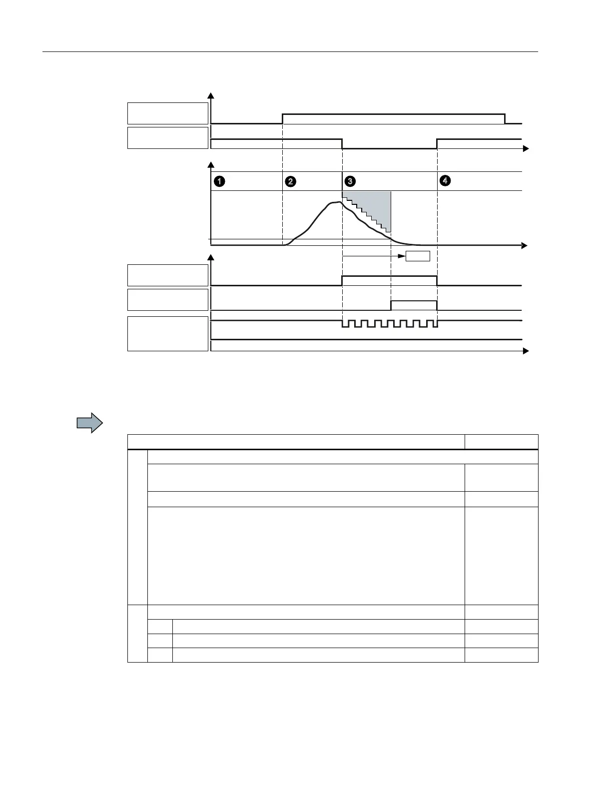
Figure A-5 Diagram 2 - acceptance test for SS1 with acceleration monitoring
Procedure
To perform the acceptance test of the SS1 function, proceed as follows:
Status
1. The inverter is ready
● The inverter signals neither faults nor alarms of the safety functions
(r0945[0…7], r2122[0…7]).
● SS1 is not active (r9722.1 = 0).
Go online with the STARTER and configure the following trace:
● Trigger on variable - bit pattern (r9720.1 = 0)
● Record the following values: r9714[0], r9714[1], r9722
Display the bits r9722.0/.1
● Select the time interval and pretrigger so you can recognize the selection
of SS1 and the transition into the subsequent STO state.
● Start the trace.
2. Switch on motor
2.1. Enter a speed setpoint ≠ 0.
2.2. Switch on the motor (ON command).
2.3. Check that the correct motor is running.
Appendix
A.2 Examples of acceptance tests
Safety Integrated - SINAMICS G110M, G120, G120C, G120D and SIMATIC ET 200pro FC-2
390 Function Manual, 01/2017, FW V4.7 SP6, A5E34261271B AD

 Loading...


