Status
2. Switch on motor
2.1. Enter a speed setpoint > SLS level.
2.2. Select SLS with the SLS level to be tested.
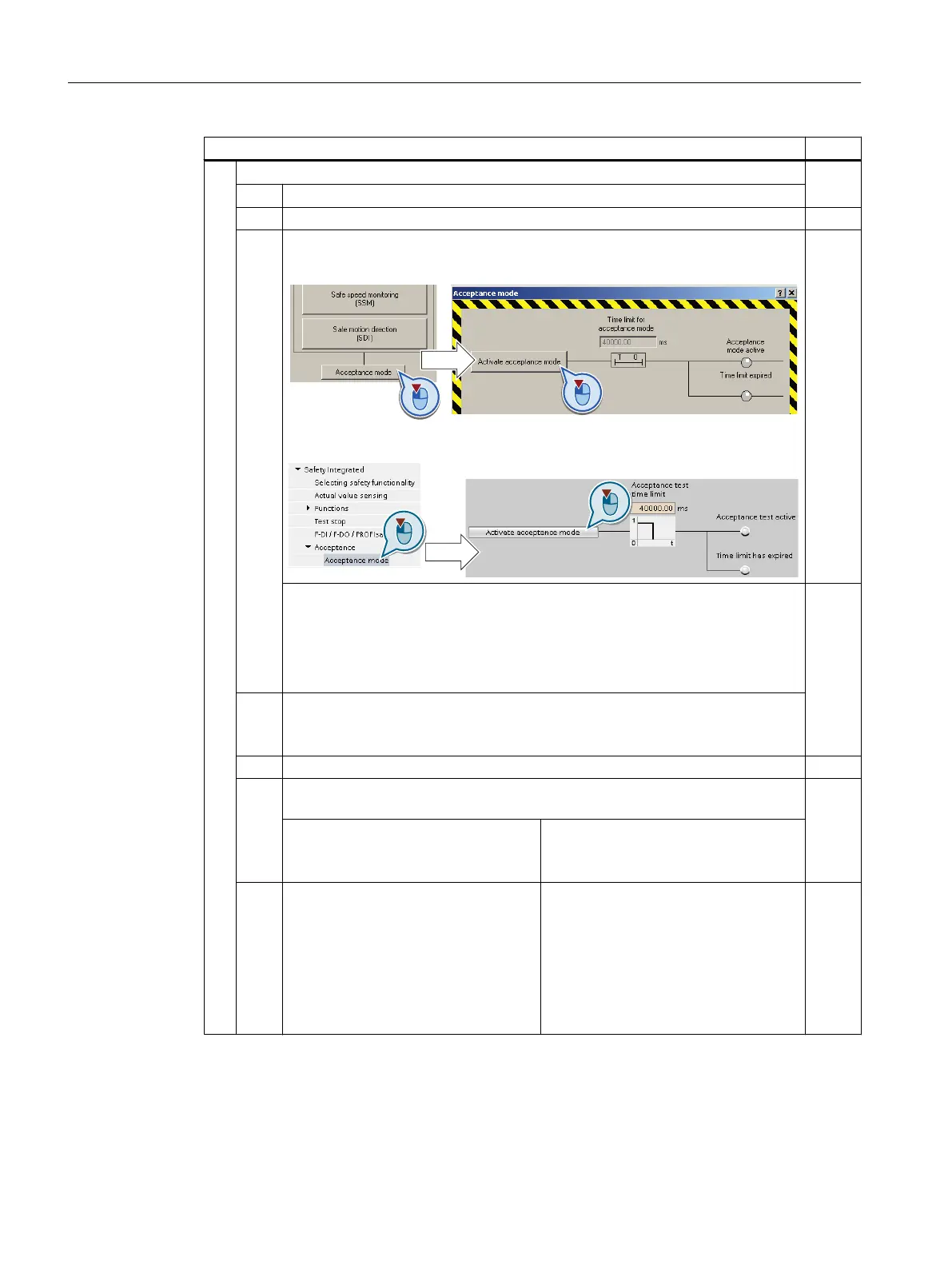
2.3. Activate the acceptance mode:
In STARTER:
In Startdrive:
WARNING
Machine motion hazard
In the following test, speed limitation of the SLS function is deactivated. The in‐
creased motor speed can lead to material damage or physical injury.
● For this test, secure dangerous machine parts using barriers, for example.
2.4. Switch on the motor within 5 seconds after selecting SLS (ON command).
If you wait longer than 5 seconds for the ON command, then STO is activated. In
this case, deselect SLS and then select it again.
2.5. Check that the correct motor is running.
The following tests depend on how you have set the SLS function during com‐
missioning:
Diagram 1:
The inverter responds with STOP A in
the event of a limit violation.
Diagram 2:
The inverter responds with STOP B in
the event of a limit violation.
2.6. The inverter signals the following:
● C01714 and C30714 (safe velocity
limit exceeded)
● C01700 and C30700 (STOP A
initiated)
The inverter signals the following:
● C01714 and C30714 (safe velocity
limit exceeded)
● C01701 and C30701 (STOP B
initiated)
● C01700 and C30700 (STOP A
initiated)
Appendix
A.2 Examples of acceptance tests
Safety Integrated - SINAMICS G110M, G120, G120C, G120D and SIMATIC ET 200pro FC-2
396 Function Manual, 01/2017, FW V4.7 SP6, A5E34261271B AD

 Loading...


