PM-switching and PP-switching fail-safe digital outputs
Depending on the particular inverter, you may connect the following fail-safe digital outputs to
a fail-safe digital input.
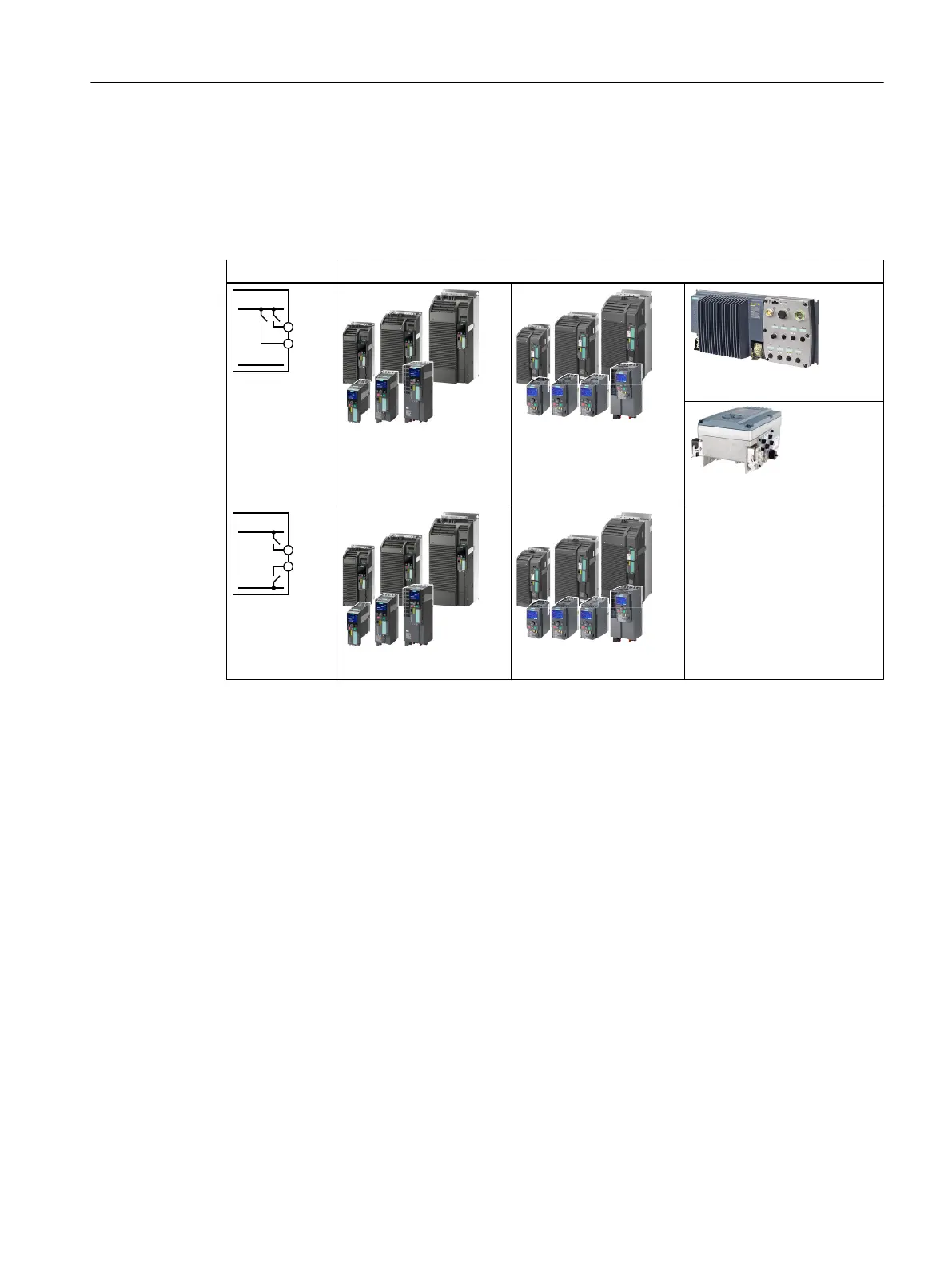
Table 4-16 PP-switching or PM-switching fail-safe digital outputs
Output It is permissible to connect the output to the following inverter and Power Module:
PP switching
output
SINAMICS G120
SINAMICS G120C
SINAMICS G120D
SINAMICS G110M
PM switching
output
SINAMICS G120
SINAMICS G120C
Fault detection
The inverter compares the two signals of the fail-safe digital input. The inverter thus detects,
for example the following faults:
● Cable break
● Defective sensor
The inverter cannot detect the following faults:
● Cross-circuit of the two cables
● Short-circuit between signal cable and 24 V power supply
Special measures to prevent cross-circuits and short-circuits
The routing of cables over longer distances, e.g. between remote control cabinets, increases
the risk of damaging cables. Damaged cables raise the risk of an undetected cross-circuit with
power-conducting cables laid in parallel. A cross-circuit can cause interruption to the transfer
of safety-related signals.
To reduce the risk of cable damage, you need to lay signal lines in steel pipes.
Installing
4.4 Controlling via a fail-safe digital input
Safety Integrated - SINAMICS G110M, G120, G120C, G120D and SIMATIC ET 200pro FC-2
Function Manual, 01/2017, FW V4.7 SP6, A5E34261271B AD 61

 Loading...


