cles in CYCLE mode
5
© Siemens AG, 2002. All rights reserved
5-98 SINUMERIK 840D/810D Operator's Guide ManualTurn (BAM) – 08.02 Edition
Parameters for hole circle drilling
Peripheral end Face plane
F
Feedrate (only with drilling peripheral/face)
If you are drilling with a second spindle that is not supported by
ManualTurn, the feedrate can only be entered in mm/min.
Please follow the advice of the machine manufacturer.
S2 (alternative)
Spindle speed of the second spindle with specification of the rotation
direction.
P
Tool lead (only for peripheral/face thread).
Full/circle segment (altern.)
Selection circle patterns
Peripheral end
Z0
Absolute coordinate Z
N
Number of holes
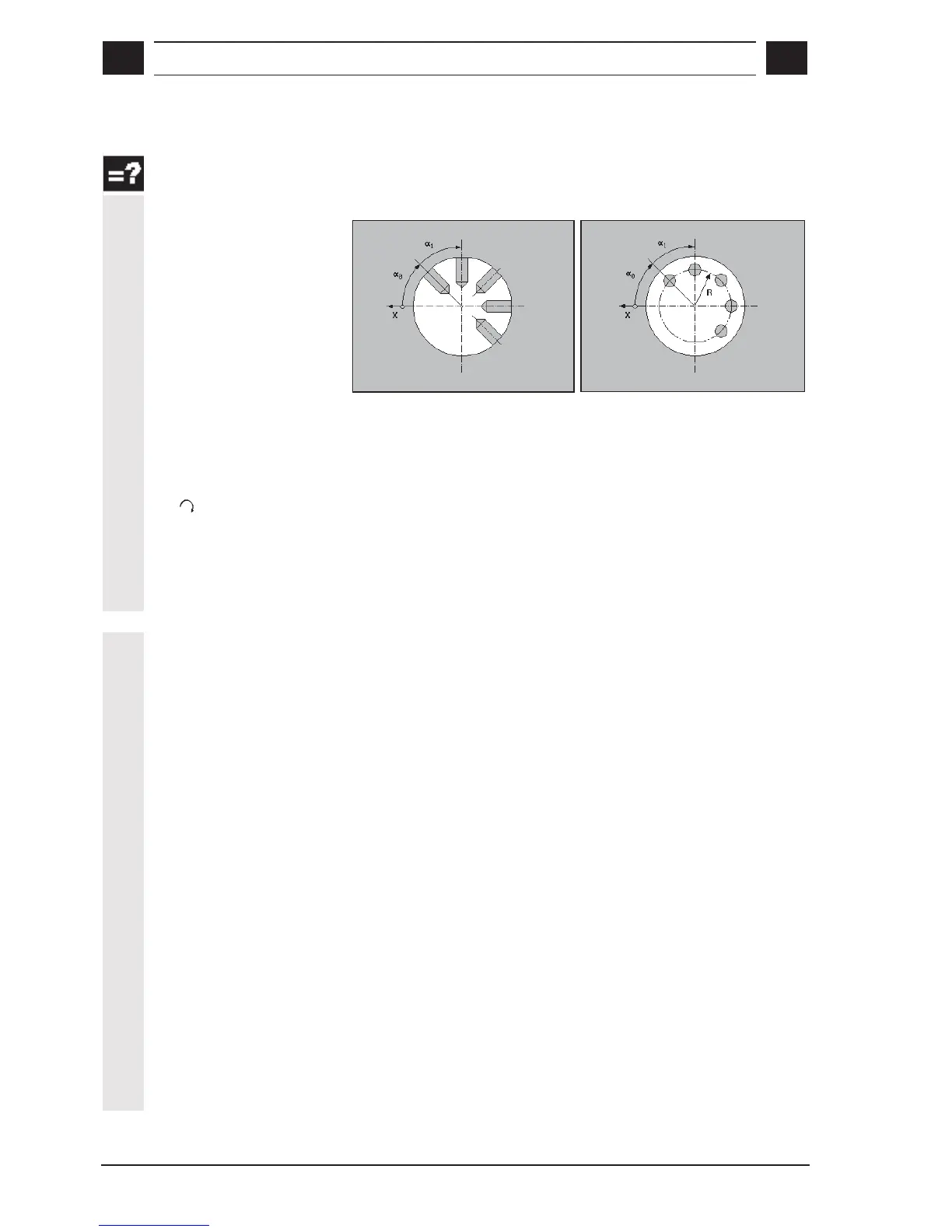
α
αα
α0
Base rotation angle
This parameter defines the location of holes in the hole circle.
Parameter
α
αα
α0 defines the base rotation angle of the first hole in
reference to the X axis.
α
αα
α0 >0: full circle/circle segment is rotated counterclockwise
α
αα
α0 >0: full circle/circle segment is rotated clockwise
α
αα
α1
Advance angle
Parameter
α
αα
α1 contains the angle of rotation from one hole to the next
and is only needed for setting parameters for a circle segment. If the
value of parameter
α
αα
α1 is zero, the advance angle is calculated in the
cycle from the number of holes, such that they are evenly distributed
along the circle.
α
αα
α1 >0: further positions are rotated counterclockwise.
α
αα
α1 <0: further positions are rotated clockwise.
X0
Reference point; corresponds to the diameter of the peripheral which
is to be drilled into.
For drilling behind the turning center, you must enter a negative
parameter value.

 Loading...


