cles in STOCK REMOVAL mode
5
© Siemens AG, 2002. All rights reserved
SINUMERIK 840D/810D Operator's Guide ManualTurn (BAM) – 08.02 Edition 5-107
Explanation of parameters
As an example for all grooving cycles, the parameters for the cycle
stored under soft key 8 are explained below. The parameter
description applies equally to the remaining two grooving cycles.
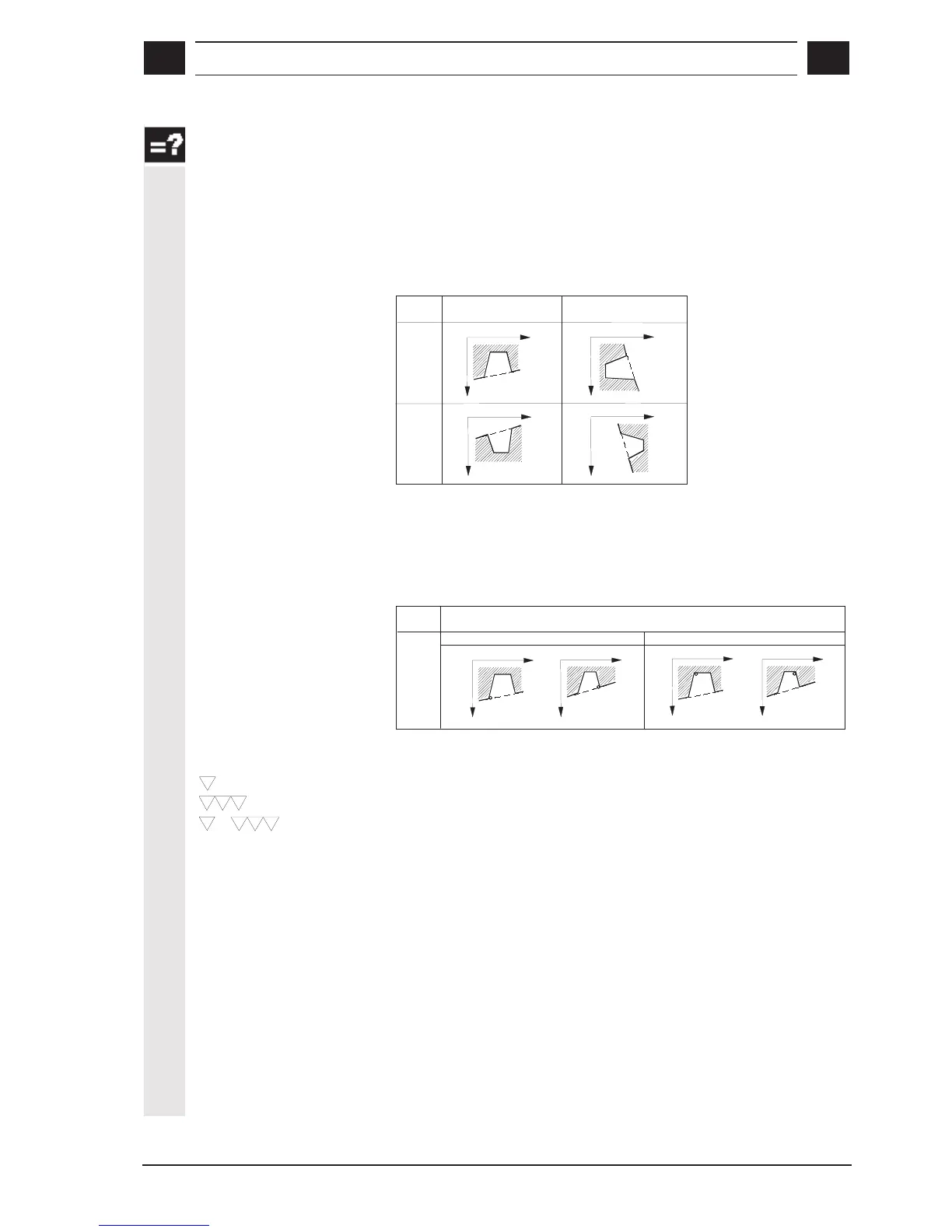
Position
The position of the groove in the coordinate system is defined by
means of this setting.
X
X
Z
Z
X
X
Z
Z
External
Internal
Position
Longitudinal groove
Face groove
Reference point
You define the reference point on the groove base (reference point
bottom) or the groove edge (reference point top) depending on the
position in the coordinate system.
e.g. for an external longitudinal groove, the following options can be
selected:
X
X
ZZ
External
Position
Longitudinal groove
X
X
ZZ
Reference point top Reference point bottom
Machining mode
Select one of the following machining modes:
+
Roughing
Finishing
Complete machining (roughing and finishing)
X0, Z0
Reference points for dimensioning
These coordinates define the point of a groove from which the cycle
calculates the groove form.
B1, B2
B
1
= Groove width, bottom
B
2
= Groove width, top
T1, T2
T
1
= Settable depth at reference point
T
2
= Depth opposite reference point
Set the groove width B1, B2 and groove depth T1, T2
parameters to
define the groove form. The cycle always bases its calculations on the
point programmed under
X0 and Z0.

 Loading...


