Examples
4.1 Definition and activation of protection zones
Axis Monitoring, Protection Zones (A3)
4-2 Function Manual, 08/2005 Edition, 6FC5397-0BP10-0BA0
3
:
;
;
0
5
=
)
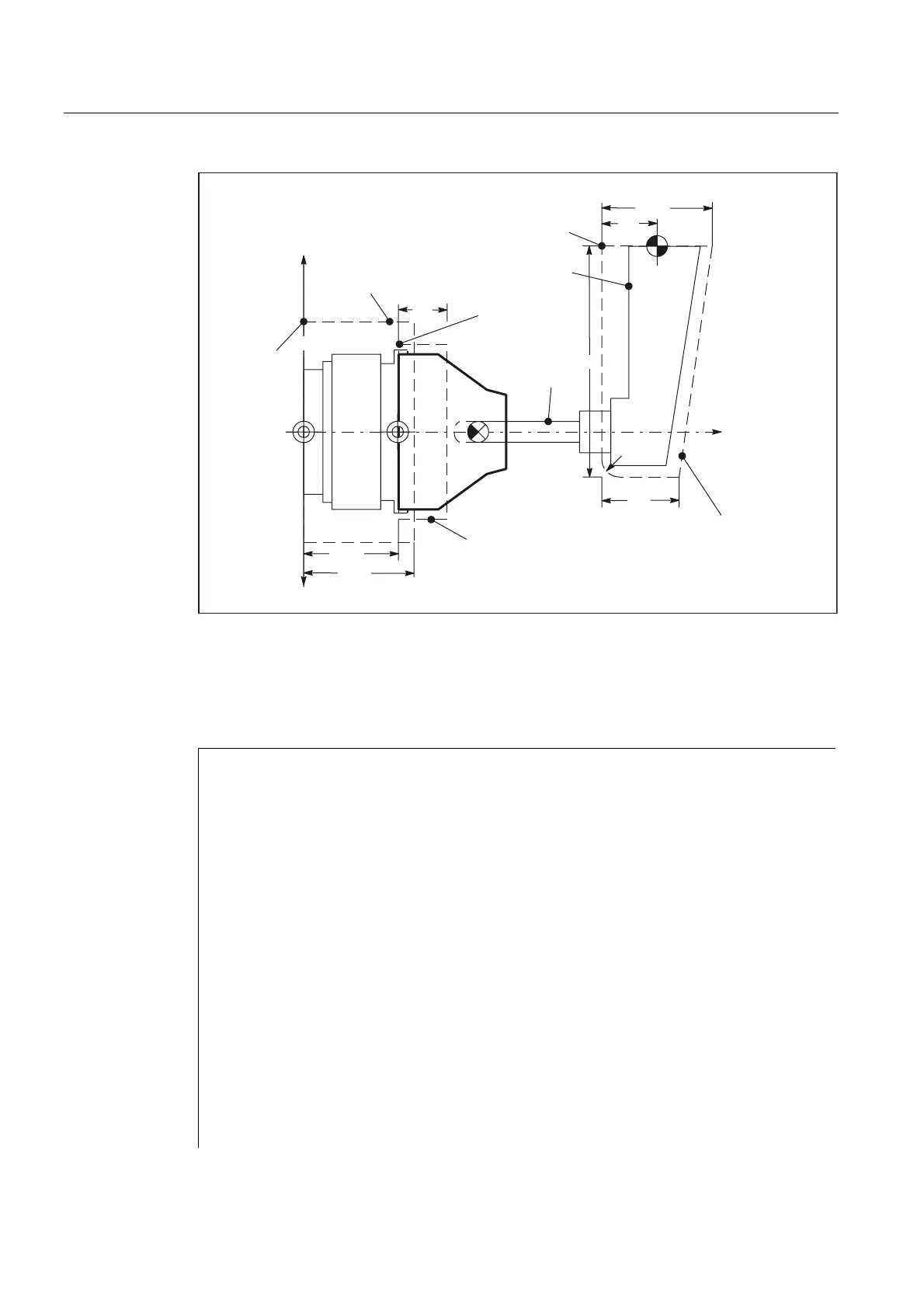
7RROKROGHU
'ULOO
6WDUWSRLQW
6WDUWSRLQW
3URWHFWLRQ]RQHIRU
VSLQGOHFKXFN
3URWHFWLRQ]RQH
IRUZRUNSLHFH
6WDUWSRLQW
3URWHFWLRQ]RQH
IRUWRROKROGHU
Fig. 4-1 Example of protection zones on a lathe
Protection zone definition in the part program
Table 4-1 Part program excerpt for protection zone definition:
DEF INT AB
G18 ; Definition of the working plane
NPROTDEF(0,FALSE,0,0,0)
NPROTDEF(1,FALSE,0,0,0) ; Definition beginning: Protection zone
for spindle chuck
G01 X100 Z0 ; Contour description: 1. Contour element
G01 X-100 Z0 ; Contour description: 2. Contour element
G01 X-100 Z110 ; Contour description: 3. Contour element
G01 X100 Z110 ; Contour description: 4. Contour element
G01 X100 Z0 ; Contour description: 5. Contour element
EXECUTE(AB) ; End of definition: Protection zone for
spindle chuck
CPROTDEF(1,FALSE,0,0,0) ; Definition beginning: Protection zone
for workpiece
G01 X80 Z0 ; Contour description: 1. Contour element
G01 X-80 Z0 ; Contour description: 2. Contour element
G01 X-80 Z40 ; Contour description: 3. Contour element
G01 X80 Z40 ; Contour description: 4. Contour element
G01 X80 Z0 ; Contour description: 5. Contour element
 Loading...


