Detailed Description
2.4 Tool: Tool radius compensation 2D (TRC)
Tool Compensation (W1)
Function Manual, 08/2005 Edition, 6FC5397-0BP10-0BA0
2-39
2.4 2.4 Tool: Tool radius compensation 2D (TRC)
2.4.1 General
Note
For TRC (tool radius compensation), see:
References:
/PA/ Programming Guide, Fundamentals.
Only the Programming Guide contains a complete technical description of TRC (Tool Radius
Compensation) and its special aspects.
Why TRC?
The contour (geometry) of the workpiece programmed in the part program should be
independent of the tools used in production. This makes it necessary to draw the values for
the tool length and tool radius from a current compensation memory. Tool radius
compensation can be used to calculate the equidistant path to the programmed contour from
the current tool radius.
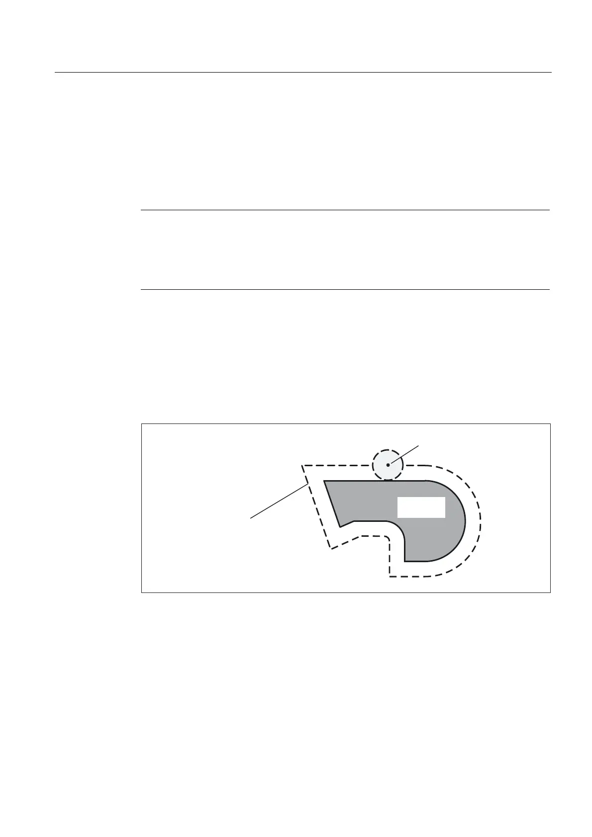
7RRO
3DWKRIWKHWRROFHQWHUSRLQW
DWHTXDOGLVWDQFHWRWKH
FRQWRXUHTXLGLVWDQWSDWK
:RUNSLHFH
FRQWRXU
Fig. 2-14 Workpiece contour (geometry) with equidistant path
 Loading...


