Detailed description
2.6 Interface structure
Power Line Basic PLC Program (P3)
2-36 Function Manual, 08/2005 Edition, 6FC5397-0BP10-0BA0
%\WH
'%
1&.
6WDWXVVLJQDOV
*ULQGLQJ
7HFKQRORJ\
&RQWUROVLJQDOV
5HVHUYH
,1&PRGH
VHOHFWLRQ
WKURXJK
B)&
B)&
YDOXHVRI06DQG)GLVWULEXWRUVRIEDVLFSURJUDP
$[LV
VSLQGOH
GULYH
6WDWXVVLJQDOV
06YDOXH
6WDWXVVLJQDOV
6HWJHDUVWDJH
$[LDO)YDOXH
6WDWXVVLJQDOV
$FWLYH,1&PRGH
6WDWXVVLJQDOV
'ULYHVLJQDOV
6SLQGOH
VLJQDOV
$[LVVLJQDOV
6KDUHG
D[LVVSLQGOH
VLJQDOV
*ULQGLQJ
7HFKQRORJ\
&RQWUROVLJQDOV
'ULYHVLJQDOV
$[LVVLJQDOV
/LPLWVZLWFK
&RQWUROVLJQDOV6SLQGOHVLJQDOV
6KDUHG
D[LVVSLQGOH
VLJQDOV
,1&PRGH
7UDYHUVHVLJQDOV
&RQWUROVLJQDOV
)HHGUDWHVSLQGOH
RYHUULGH
%3
0&3
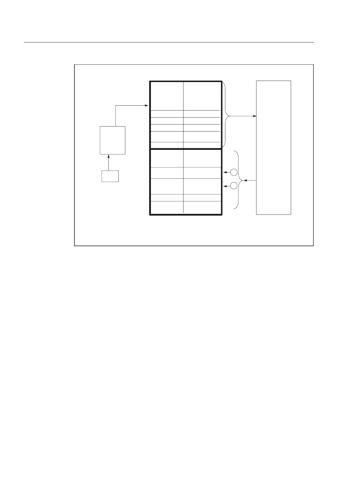
Fig. 2-7 Interface between PLC and axes/spindles/drives
2.6.2 PLC/MMC interface
General
The following groups of functions are required for the PLC/MMC interface:
• Control signals
• Machine operation
• PLC messages
• PLC status display
Control signals
In some cases, signals are input via the machine control panel and must be taken into
account by the MMC. This group of signals includes, for example, display actual values in
MCS or WCS, key disable, etc. These are exchanged with the MMC via a separate interface
DB (DB19).
 Loading...


